CHA NGE PARA METERS 105
6.8.12 CURRENT C ON TROL / Discontinuous current point PIN 95
This can be set by usi ng the AUTOTUNE function. The motor/supply combination will possess a property
called the discontinuous-continuous current point w hich is important for optimum tuning of the current loop.
If you change your supply voltage, current calibration or motor type then re-adjust this parameter.
6.8.12.1 Setting the current loop control terms manually.
As the current increases there comes a point when the current stops appearing in 6 discrete lumps per cycle
and just starts going continuous. At this point the natural gain of the system changes dramatically. If the unit
knows this point, it can automatically compensate for the gain change and produce an optimum response.
The current level % of rated motor current at which it occurs is entered here. If you change your supply
voltage, current calibration or motor type, the 3 values for PINs 93/94/95 must be adjusted accordingly.
To observe the current signal you must use the signal test pin provided, and a quality storage oscilloscope.
See 3.4.5 Signal test pins. Monitor 134)ARM CUR % MON to monitor the % value at the boundary.
Use the table to determine the other current loop control terms
134)ARM CUR % M O N
at boundary point
Suggested value for
93)CUR PROP G AIN
Suggested value for
94)CUR INT G AIN
10.00 % 40.00 4.00
20.00 % 20.00 2.00
40.00 % 10.00 1.00
60.00 % 10.00 1.00
80.00 % 10.00 1.00
100.00% 10.00 1.00
6.8.13 CURRENT C ONTROL / 4 quadrant mode enable PIN 96
If 96)4-Q U A DRA NT MODE is enabled then the regenerative capability will be determined by the model.
See 3.3 General Technical Data. Note. PL models with regenerative stopping. This feature is also dis/enabled.
6.8.14 CURRENT C ON TROL / Speed bypass current reference enable PIN 97
There is an internal connection from T3 via UIP3 to 64)SPEED REF3 MON. This parameter determines
whether T3 is a speed or current reference. If enabled, the speed loop output is automatically disconnected.
Note. The summing junction for this input is shown in 6.7.1 SPEED CONTROL / Block diagram.
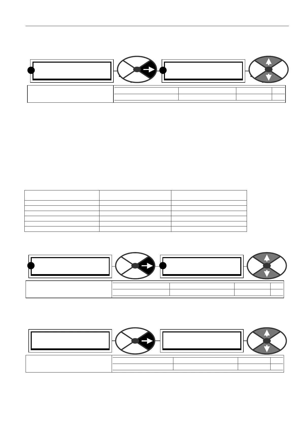
CURRENT C ON TROL 3
95)C UR DISC ONTINUITY
95)C UR DISC ONTINUITY
13.00 %
PARA METER RANGE DEF AULT PIN
CUR DISC ONTINUITY 0.00 to 200.00 % 13.00 % 95
Set to the discontinuous current
boundary level for your motor.
R
R
CURRENT C ON TROL 3
96)4-Q U A DRA NT MODE
96)4-Q U A DRA NT MODE
EN ABLED
PARA METER RANGE DEF AULT PIN
4-QUA DRANT M ODE ENABLED or DIS ABLED EN ABLED 96
Allo ws models with regenerative
capability to be 2 quadrant.
R R
CURRENT C ON TROL 3
97)SPD BYPASS CUR EN
97)SPD BYPASS CUR EN
DISABLED
PARA METER RANGE DEF AULT PIN
SPD BYPASS CUR EN ENABLED OR DIS ABLED DIS ABLED 97
Allo ws a current reference input
which by-passes the speed loop.