106 CHA NGE PARA METERS
6.9 CHANGE PARAMETERS / FIELD CONTROL
PIN number range 99-114
The field controller within the PL/X consists of a
single phase half controlled thyristor bridge with a
fly wheel diode. The A C supply to the bridge is
delivered through terminals EL2 and EL3, and the
rectified output is on terminals F + and F-. The
supply can be any w here in the range of 100 to
480V A C, but must, at least, be 1.1 times the
maximum field output voltage you require.
Note that the supply to EL2 and EL3 is also utilised
to determine phase rotation of the local supply.
The purpose of the field winding in a motor is to
provide flux that intersects the armature windings.
The flux generated is a function of the CURRENT
flo wing in the field coils. When considering the set
up of the field output you are able to use 1 of 2
types of control strategy.
1) Voltage clamp with higher current limit
protection.
2) Current control with higher voltage clamp
protection.
Motor field windings are normally very inductive and
have a long time constant. This results in smooth
current in the field. In this case the field current
reading is reasonably accurate irrespective of when
it is sampled.
Some motors have shorter field winding time constants than normal resulting in up to 20 % ripple. In this
case the PL/X may sample the current at a non-ideal point in the cycle which will result in a slightly incorrect
control level. (Usually no more than a few %) To normalise the field current back to its correct level it may be
necessary to use the field current trim. See 6.1.12 C ALIBRA TION / Field current feedback trim PIN 15, or
re-calibrate the field current to overcome the inaccuracy.
Warning. Field reversal or disconnection.
Due to the high inductance of motor fields it may take several seconds for the field current to decay to zero
after the field output has been inhibited by the PL/X. Do not open circuit the fiel d unless the field curr ent has
reached zero. The PL/X is unable to measure the decaying current after an inhibit, so it is not possible to use
the field current monitors or field active flag to show zero current has actually been attained. It is necessary
to observe the current on an external instrument and time how long it takes to decay. The interval timer
block may then be utilised to implement a safety delay before opening the fiel d circuit.
Failure to observe this w arning may cause flashover of the field circuit and result in damage to the system.
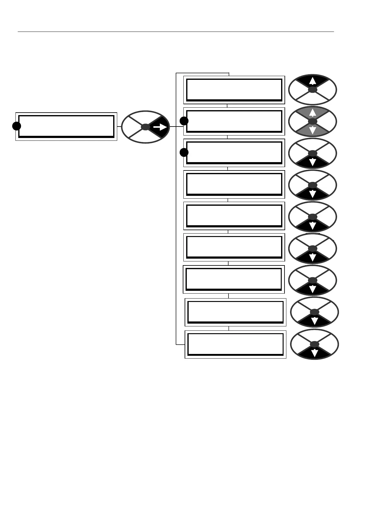
CH A NGE PARA METERS 2
FIELD C ONTROL 3
R
FIELD C ONTROL 3
114)FIELD REFERENCE
FIELD C ONTROL 3
99)FIELD EN ABLE
FIELD C ONTROL 3
FLD WE A KENING MENU 4
FIELD C ONTROL 3
100)FIELD V OLTS OP %
FIELD C ONTROL 3
101)FIELD PROP G AIN
FIELD C ONTROL 3
102)FIELD INT G AIN
FIELD C ONTROL 3
111)ST A NDBY FLD ENBL
R
R
FIELD C ONTROL 3
112)ST A NDBY FLD CUR
FIELD C ONTROL 3
113)FLD Q UEN CH DELA Y