68 CHA NGE PARA METERS
6.1.11 C ALIBRA TION / IR compensation PIN 14
This parameter is used when armature voltage speed feedback type is selected or in field weakening mode.
Note. Speed is proportional to the back EMF of the motor. Back EMF = A VF – IR drop.
Hence when the armature current is high the IR drop is high. At zero armature current the IR drop is zero.
To set this parameter with A VF feedback, arrange if possible to apply a significant load change to the
system. Slowly increment the parameter until the load change has minimum effect on the speed holding.
Alternatively calculate the parameter using the formula belo w and initially enter this value.
IR C OMPENS ATION (%) = RA TED MOT OR A MPS X Armature resistance X 100 / RA TED ARM V OLTS.
Note. Excessive compensation may lead to instability.
See also 6.9.6 FIELD CONTROL / FLD WEA KENING MENU for field w eakening systems.
6.1.12 C ALIBRA TIO N / Field current feedback trim PIN 15
This trim factor may be applied during drive running. The factor is al ways greater than unity hence can only
increase the strength of the feedback. The closed loop system then receives feedback that is too high and
causes a reduction of the controlled field current.
(This trim is useful if the precise 4)RA TED FIELD A MPS calibration parameter is not exactly known and must
be discovered during running by starting with a higher than expected value. Once the correct level of
feedback has been determined using this trim (the DIAGNOSTICS menu can be used to monitor actual levels
of feedback), it can then be entered in the 4)RATED FIELD AMPS calibration parameter. This trim may then
be returned to 1.000).
6.1.13 C ALIBRA TION / Armature volts trim PIN 16
This trim factor may be applied during drive running. The factor is al ways greater than unity hence can only
increase the strength of the feedback. The closed loop system then receives feedback that is too high and
causes a reduction of the armature voltage feedback and hence a reduction in speed.
(This trim is useful if the precise 18)RA TED ARM V OLTS calibration parameter is not exactly known and
must be discovered during running by starting with a higher than expected value. Once the correct level of
feedback has been determined using this trim, (the DIA GNOSTICS menu can be used to monitor actual levels
of feedback), it can then be entered in the 18)RATED ARM V OLTS calibration parameter. This trim may then
be returned to 1.000).
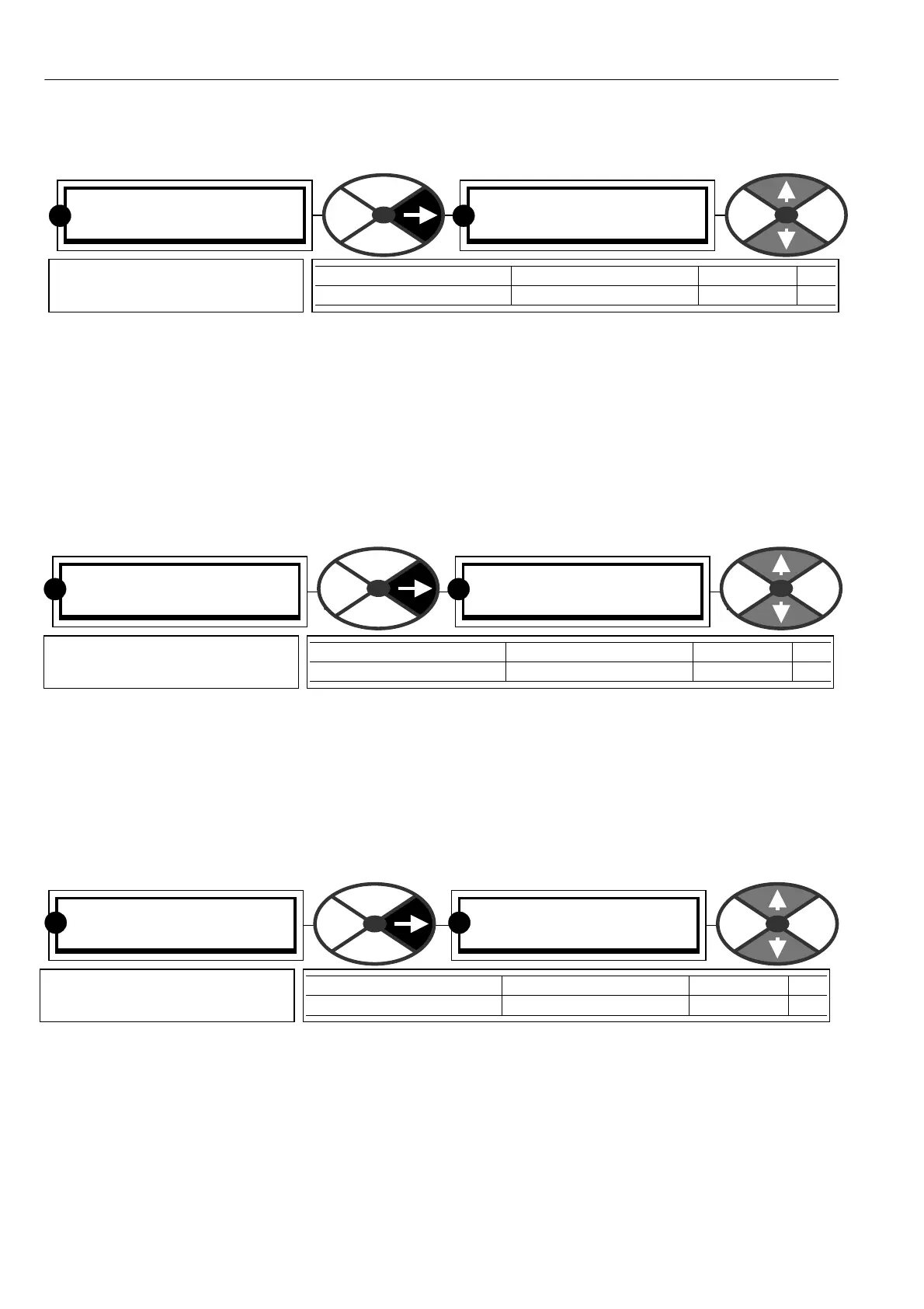
C ALIBRA TIO N 3
14)IR COMPENS A TION
14)IR COMPENS A TION
0.00 %
PARA METER RANGE DEFAULT PIN
IR C OMPENS ATION 0.00 to 100.00% 0.00 % 14
Sets % compensation of the
A V F signal due to IR drop
RR
C ALIBRA TIO N 3
15)FIELD CUR FB TRIM
15)FIELD CUR FB TRIM
1.0000
PARA METER RANGE DEFAULT PIN
FIELD CUR FB TRIM 1.0000 to 1.1 00 0 1.0000 15
Sets a positive trim factor for
the field current feedback
R
R
C ALIBRA TIO N 3
16)ARM V OLTS TRIM
16)ARM V OLTS TRIM
1.0000
PARA METER RANGE DEFAULT PIN
ARM V OLTS TRIM 1.0000 to 1.1000 1.000 0 16
Sets a positive trim factor for
the armature volts feedback
RR