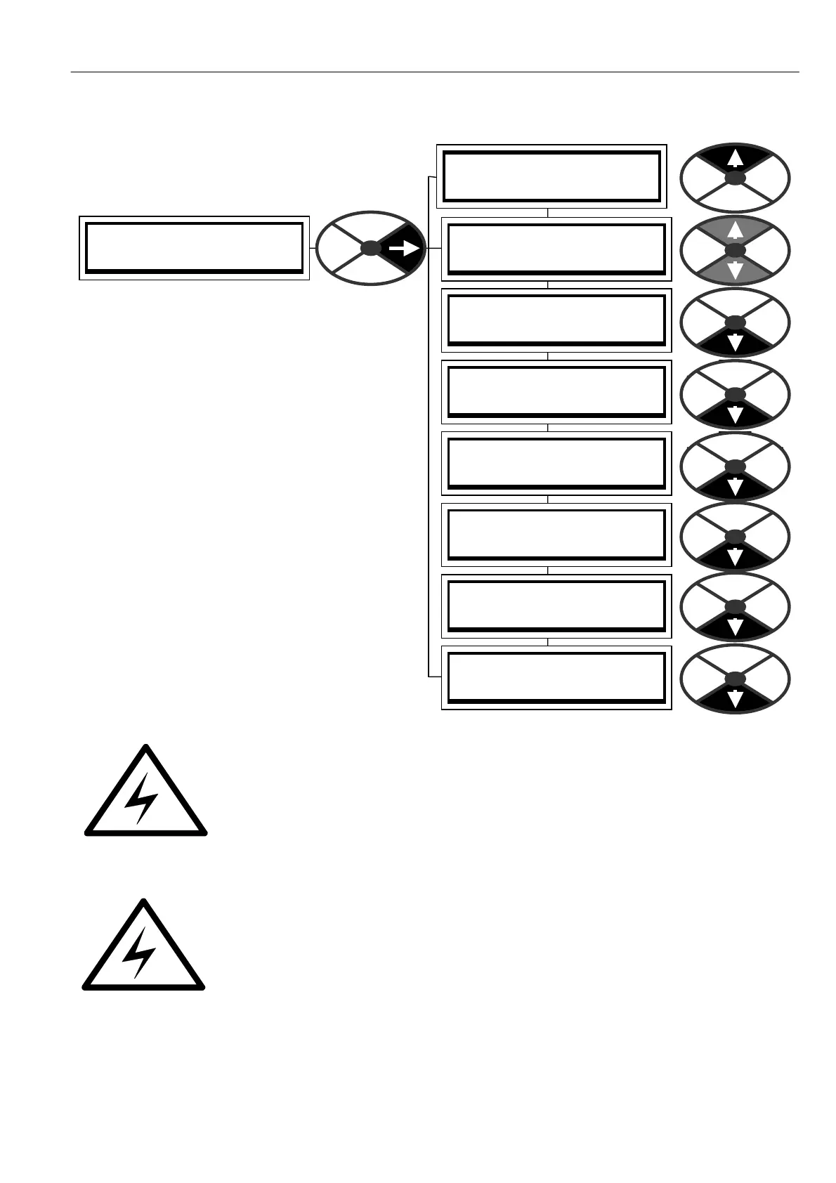
CHA NGE PARA METERS 109
FIELD C ONTROL 3
FLD WE A KENING MENU 4
FLD WE A KENING MENU 4
110)MIN FLD CURRENT
FLD WE A KENING MENU 4
103)FLD WEA K ENABLE
FLD WE A KENING MENU 4
104)FLD WK PROP G AIN
FLD WE A KENING MENU 4
105)FLD WK INT TC ms
FLD WE A KENING MENU 4
106)FLD WK DRV TC ms
FLD WE A KENING MENU 4
107)FLD WK FBK DRV ms
FLD WE A KENING MENU 4
108)FLD WK FBK INT ms
FLD WE A KENING MENU 4
109)SPILLOVER A V F %
6.9.6 FIELD CONTROL / FLD WEAKENING MENU
The function must be ENABLED to control field
weakening.
There are 5 c ontrol terms that can be adjusted.
These are 3 error te rms, derivative, proportional
and integral , plus 2 feedback terms, derivative and
integral. All these terms are associated with the
armature voltage spillover loop and they are chosen
to give the best response without excessive
overshoots or instability of the armature voltage.
The control loop monitors the armature voltage and
compares it to the desired spillover voltage. It then
controls the field current to optimise the speed
control of the drive in the field w eakening region.
When the armature voltage reaches the spillover
voltage, further speed increases are achieved by
field weakening, and the armature voltage is
effectively clamped at the spillover voltage. In this
region the output po wer is constant for a given
armature current.
See. 6.1.11 C ALIBRA TIO N / IR compensation PIN 14. Further accuracy can be achieved with IR CO MP.
WARNING. When using field weakening and a DC side power contactor, the motor
armature must be connected to the REMOTE AV sensing terminals T41 and T43.
Failure to do this will cause flashover of the commutator because the AVF feedback is
lost when the contactor opens.
WARNING. Do not use field weakening if Armature Voltage Feedback is selec ted in the CALIBRATION menu.
If A VF has been selected, and field weakening enabled, then if the field w eakening region is entered the drive
will trip. Note. The action of changing feedback mode to A V F will automatically rescale
the 100 % speed feedback to refer to 18)RA TED ARM V OLTS. To continue running in
this mode (e.g. if tacho has failed) and avoid tripping, ensure the field w eakening region
is avoided by remaining at a speed which gives an armature voltage below
109)SPILLOVER A V F %.
130)MOTOR RPM monitor will read incorrectly unless 6)DESIRED M A X RPM is
readjusted to base RPM.
If this trip occurs the DRIVE TRIP MESSAGE will be SPEED FBK MISM A T CH.
Note. The limit of field weakening range is 10 : 1.
See 8.1.1 MO TOR DRIVE ALARMS / Speed feedback mismatch trip enable PIN 171.