CHA NGE PARA METERS 63
6.1.8 C ALIBRA TION / Max tacho volts PIN 8
Multiply the output volts per rev value for the tacho by the full speed rpm of the tacho
e. g. 1 tacho rating = 0.0 6 V per rev, 10 0% speed of tacho = 500 rpm, then tacho scaling = 30.00 V
e. g. 2 tacho rating = 0.0 9 V per rev, 10 0% speed of tacho = 2000 rpm, then tacho scaling = 180.00V
Alternatively, for systems NOT employing field w eakening, run the system in A VF at desired full speed and
monitor the tacho volts. See 7.1.7 SPEED LOOP MONITOR / Tachogenerator volts monitor PIN 129, then
after entering the observed full speed tacho volts, convert to tacho feedback. See 3.4.4 Analogue
tachogenerator input, also 6.1.9 C ALIBRA TIO N / Speed feedback type PIN 9 QUICK ST ART.
The sign of the parameter should correspond to the sign of the tacho volts for positive speed demand.
For tacho volts which exceed 200V full scale, it is necessary to provide an external resistor dropper network
as follows.
The network sho wn will allo w full scale voltages up to 40 0 Volts. The number scrolled in the window should
be set to half the full scale tacho volts. Appropriate measures must be taken to dissipate the heat from the
dropper resistors. The total po w er in watts dissipated will be (Tacho signal volts)
2
/ 20,000.
There is a tacho failure detection system that may be configured to either trip the drive, or automatically
switch to A VF. See 8.1.1 MOT OR DRIVE ALARMS / Speed feedback mismatch trip enable PIN 171.
See also 3.4.4 Analogue tachogenerator input.
10K
5W
10K
5W
Tacho
signal
Terminal 2 6
T A CHO
Terminal 2 5
0V
Resistor
Resistor
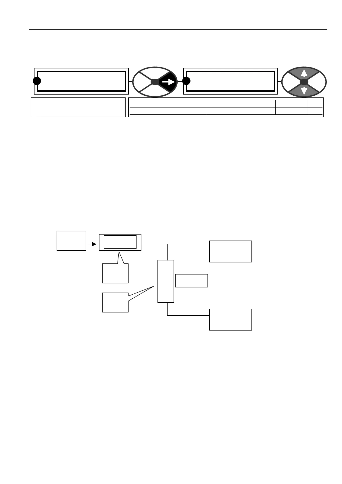
C ALIBRA TIO N 3
8)M A X T A CHO V OLTS
8)M A X T A CHO V OLTS
60.00V
PARA METER RANGE DEF AULT PIN
M A X T A CH O V OLTS + /-200.00 volts 60.0 0V 8
Scales the tacho input for full
feedback volts at 100 % speed
R R