Basic application 43
4.5.2 Quick start calibration step by step
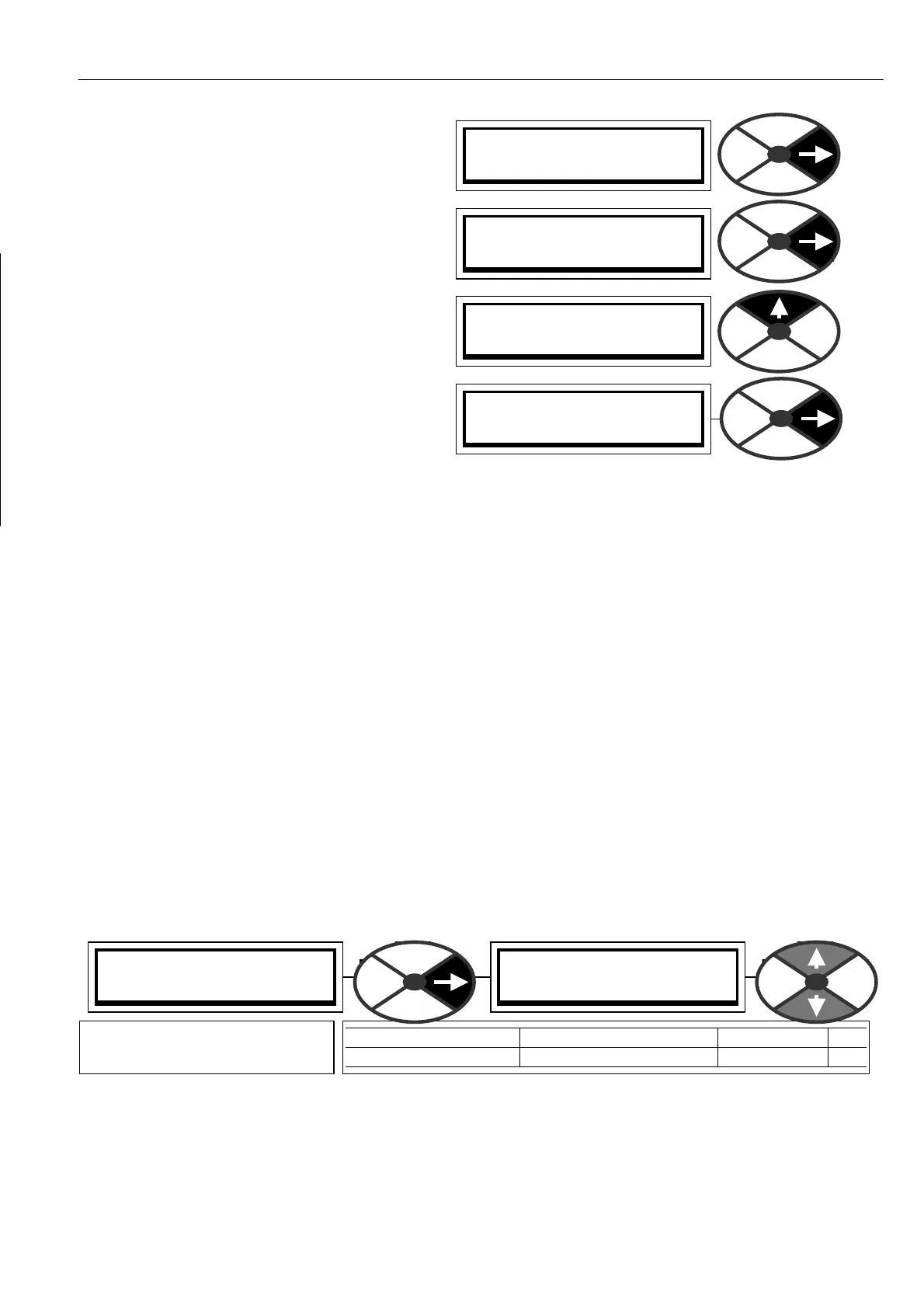
1) Turn on the control supply and press the right
key to exit diagnostics for the ENTRY MENU.
2) Press the right key to enter the ENTRY MENU
/ CH A NGE PARAMETERS window . Press the
right key again to enter the CH A NGE
PARA METERS / RUN MODE RA MPS menu. Then
press the up key for the CHAN GE PARAMETERS
/ C ALIBRA TION menu. Enter the CALIBRATIO N
menu by pressing the right key. Once there, use
the up or down key to travel round the circular
menu.)
3) Only 8 of the available parameters need to be
adjusted for Q UICK ST ART. (PINs 2, 3, 4, 5, 6,
9, 18, 19). Skip the other windo ws.
4) Select the quick start parameters by using the up / down keys. Press the right key to enter the parameter
adjustment window for each in turn. Modify each one to suit your system using the up/dow n keys. Use the
left key to back out of each parameter adjustment window and return to the circular C ALIBRATION menu.
When you have finished modifying the 8 quick start parameters, it is time to save the changes you have
made. Use the left key to return to the ENTRY MENU / CHANGE PARAMETERS menu. Use the up key to
arrive at ENTRY MENU / PARA METER S A VE. Use the right key to enter the PARA METER SA VE windo w . Use
the up key to save the parameters. While the save is taking place the bottom line will read SA VING. When
the save is complete the bottom line will read FINISHED. You can now return by holding do wn the left key.
This will take you to the default diagnostics, and then one tap right to the ENTRY MENU.
Note. For a description of the default diagnostics see 5.1.6 Default % DIA GN OSTIC summary windo ws.
Now the PL/X is calibrated to match your motor it is time to apply 3 phase po w er for the first time to
establish correct functioning of the main contactor and that the field current is correct. Remember that there
should be a fire-bar inserted in the armature circuit to protect against fault currents.
See 4.2 Main Contactor operation and 7.3 DIA GNO STICS / FLD I LOOP MONITOR.
Once you have established correct functioning of the main contactor and that the armature and field are
receiving po wer as expected, then you must remove the fire bar in readiness for the quick start procedure.
4.5.3 Quick start current loop AUTOTUNE
5) The next step is to set up the armature current loop response. The unit is provided with an autotune
facility that will perform this function automatically. Using the keys go to CHANGE PARAMETERS /
CURRENT C ON TROL, and then to CURRENT C ONTROL / AUTO TUNE EN ABLE.
Note. The autotune function makes adjustments to the current loop error amplifier PID terms to achieve
optimum performance. When ENABLED it will wait until the main contactor is energised, and the drive run,
before starting its autotune routine. It may take from a fe w seconds up to about 1 minute typically. When it
has finished it drops out the main contactor, sets the required parameters and then automatically DISABLES
itself. You can check that it has finished by looking in the display window and waiting for the DISABLED
comment to re-appear on the bottom line. This is a stationary test. There is no need to remove the load.
PRESS RIGHT KEY FOR
ENTRY MENU LEVEL 1
ENTRY MENU LEVEL 1
CH A NGE PARA METERS 2
CH A NGE PARA METERS 2
C ALIBRA TIO N 3
CH A NGE PARA METERS 2
RUN MODE RAMPS 3
CURRENT C ON TROL 3
92)AUTO TUNE EN ABLE
92)AUTO TUNE EN ABLE
DIS ABLED
PARA METER RANGE DEF AULT PIN
AUTOTUNE EN ABLE EN ABLED OR DIS ABLED DISABLED 9 2
Enables the autotune function
to start. It turns itself off.