22 Introduction and Technical Data
3.3 General Technical Data
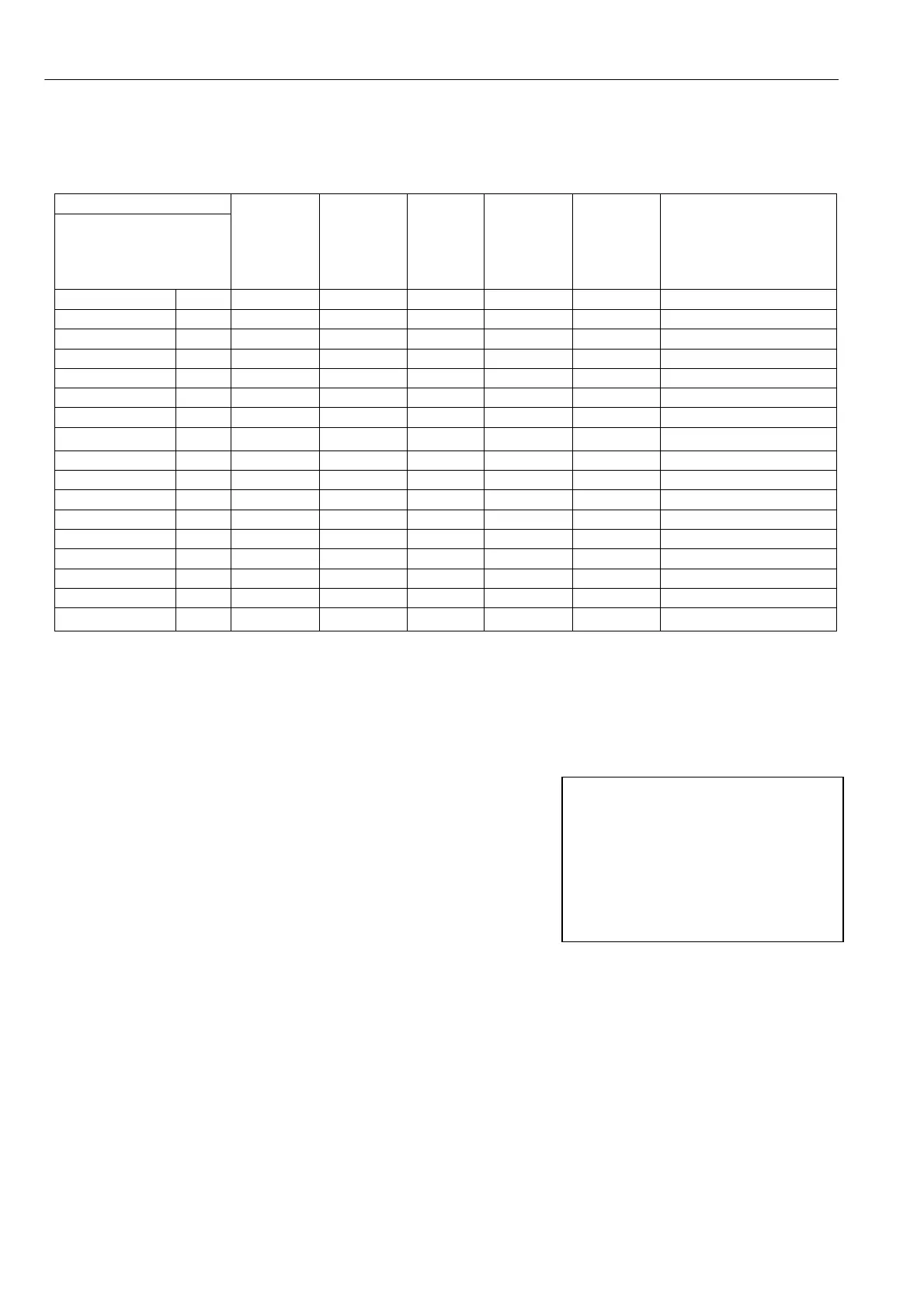
Rating table Maximum continuous shaft ratings
Model
PL 2 quadrant
PLX 4 quadrant
kW
at 460V
HP
at 460V
HP
at 500V
100%
Armature
Current
DC
Amps
100%
Field
Amps
Dimensions mm
(force vented = fv)
W x H x D
*PL and PLX 5 5 6.6 7.5 12 8 216 x 28 9 x 174
*PL and PLX 10 10 13.3 15 24 8 216 x 28 9 x 174
*PL and PLX 15 15 20 20 36 8 216 x 289 x 174
*PL and PLX 20 20 26.6 30 51 8 216 x 28 9 x 174
*PL and PLX 30 30 40 40 72 8 216 x 289 x 174 fv
*PL and PLX 40 40 53.3 60 99 8 216 x 28 9 x 17 4 fv
*PL and PLX 50 50 66.6 75 123 8 216 x 289 x 174 fv
PL and PLX 65 65 90 100 155 16 216 x 37 8 x 218 fv
PL and PLX 85 85 115 125 205 16 216 x 37 8 x 21 8 fv
PL and PLX 115 115 155 160 270 16 216 x 378 x 218 fv
*PL and PLX 145 145 190 200 330 16 216 x 378 x 218 fv
PL and PLX 185 185 250 270 430 32 or 5 0 216 x 37 8 x 314 fv
*PL and PLX 225 225 300 330 530 32 or 5 0 216 x 378 x 314 fv
PL only 265 265 350 400 630 32 or 50 216 x 378 x 314 fv
Plea se also refer to Part 3 PL/X 275-980 for extra details of frame 4 and 5 high power drives.
3.3.1 Regenerative stopping with PL models
* Starred models: (*PL) 2 Quadrant models have electronic regenerative stopping.
See 6.5.2 STOP M ODE RA MP / Stop ramp time PIN 56.
3.3.2 Supply voltages required for all models
The supplies provided must be suitable for the motor employed
Main 3 phase 50 - 6OHz
Any supply from 12 to 4 80 V A C + /- 10 % for armature power.
Auxiliary 3 phase 50 - 6OHz
Any supply from 10 0 to 480V AC + /- 10% for field power.
Control 1 phase 50 - 60Hz
Any supply from 11 0 to 240V AC + /- 10% 50 V A. This is required to power the PL/X e lectronic circuits.
PL/X 185/225/265 models also need a 50 V A 11OV 50/6OHz ac fan supply
PL/X 650-980 frame 4 and 5 high powe r drives are available as HV versions for supplies up to 690V AC.
OUTPUT VOLTAGE RANGE
Armature PLX and *PL 0 to + 1.2 times AC supply. PL 0 to + /- 1.3 times A C supply.
Note. 1.1 times A C supply is recommended if supply variations exceed –6 %.
Field 0 to 0.9 times AC supply on auxiliary terminals. (EL1, EL2, EL3)
OUTPUT CURRENT RANGE
Armature 0 to 10 0% continuous. 150% for 25 seconds + /- for PLX
Field programmable minimum to 100 % continuous with fail alarm.
Note. There is a factory option to allo w high inductance loads to be driven by the armature output.
Note. The 3 phase Field and
Armature supplies are input
through separate terminals and
may be at different levels if
desired. See 14.9.1 Wiring diagram
for A C supply to L1/2/3 different
to EL1/2/3. (E.g. Lo w voltage field)
They must however, be in phase