CHA NGE PARA METERS 97
CH A NGE PARA METERS 2
CURRENT C ON TROL 3
R
CURRENT C ON TROL 3
97)SPD BYPASS CUR EN
CURRENT C ON TROL 3
81)CUR CLA MP S C ALER
CURRENT C ON TROL 3
CURRENT O VERLO A D 4
CURRENT C ON TROL 3
I DYN A MIC PROFILE 4
CURRENT C ON TROL 3
88)DU AL I CLA MP ENBL
CURRENT C ON TROL 3
89)UPPER CUR CLA MP
CURRENT C ON TROL 3
90)LO WER CUR CLA MP
CURRENT C ON TROL 3
91)EX TRA C UR REF
CURRENT C ON TROL 3
92)AUTO TUNE EN ABLE
CURRENT C ON TROL 3
93)C UR PROP GAIN
CURRENT C ON TROL 3
94)C UR INT GAIN
CURRENT C ON TROL 3
95)C UR DISC ONTINUITY
CURRENT C ON TROL 3
96)4-Q U A DRA NT MODE
R
R
R
R
R
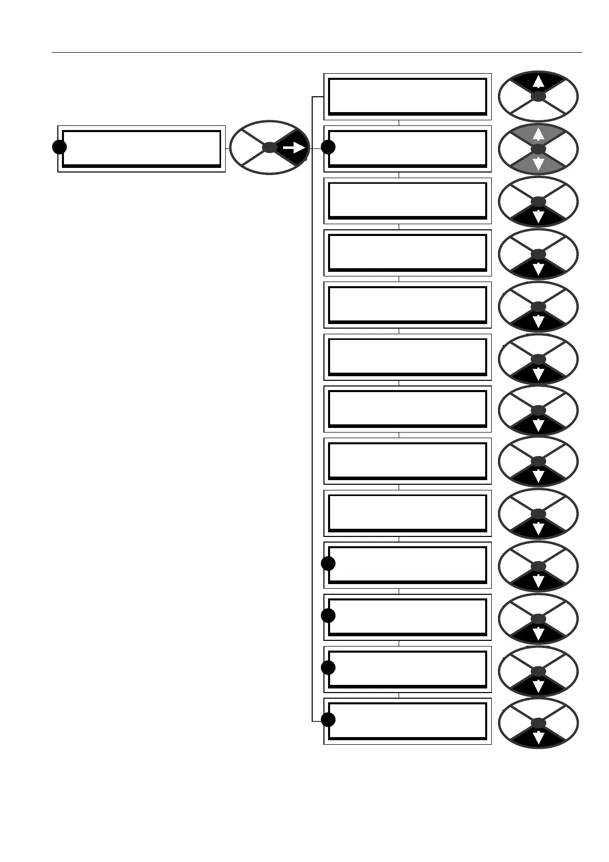
6.8 CHANGE PARAMETERS / CURRENT
CONTROL
PIN number range 81 to 9 7.
The current control menu looks fairly complex
initially, but is not too difficult to understand w hen
considered in separate blocks.
See 6.8.1 CURRENT C ONTROL / Block diagram.
The current control loop gets its current reference
from the output of the speed loop error amplifier.
The reference enters the current control section
and is subjected to a series of 4 clamps.
i3)CURRENT LIMIT(%). This provides the absolute
limits of overload. (See C ALIBRA TION menu).
ii ) CURRENT O VERLO A D. This allo ws the drive to
actively modify the current overload as it occurs.
The reduction rate of the overload is adjustable.
After an overload, the load must return below the
target level for an equivalent time, to re-enable the
overload capability.
iii) I DYN A MIC PROFILE. This clamp is used to
protect motor commutators that have problems
commutating current at high speed or in field
weakening mode of operation. This function allo ws
the setting of break points that profile the current
according to the speed.
iv) 89)UPPER CUR CLA MP and 90)LOWER CUR
CLA MP. These clamps allo w the current limits to
be adjusted from external signals. They can accept
a single positive input and produce a scaled bi-
polar clamp, or separate positive and negative
inputs for the upper clamp and lo wer clamp.
Scaling is achieved by a master current scaler.
The 4 clamps operate such that the lowest has
priority. The actual prevailing clamp level is
available as a diagnostic for + ve and –ve current.
The output of the clamping stage is referred to as
the current demand, and is compared with the
current feedback in a P + I error amplifier. The
control terms and a non-linear adaptive algorithm
are available for programming. There is also the
facility to activate a super fast current response.
See 13.13.3 DRIVE PERSONALITY / Maximum
current response PIN 678.
The output becomes the phase angle demand for the thyristor stack.