CHA NGE PARA METERS 113
6.10 CHANGE PARAMETERS / ZERO INTERLOCKS
PIN number range 115-1 21.
This menu is used to enable 2 interlocking
functions that are associated with zero speed.
There normal standstill behaviour is as follows.
After the satisfying conditions of ‘zero speed and
current demand’, AND ‘zero speed feedback’ are
fulfilled, the firing pulses are removed and all other
loops remain active to enable a rapid response for a
ne w request for speed.
117)ZERO INTLK SPD % sets the threshold for
both the zero speed reference and feedback
decisions. 118)ZERO INTLK CUR % sets the
threshold for the zero current demand decision.
If 118)ZERO INTLK CUR % is set to 0.00% then
the firing pulses are not removed.
Due to the rapid response of the above mode, it
may be necessary to implement 115)STANDSTILL
ENBL. Without this quench function enabled the
motor may be continuously moving as the system
responds to small variations, which may be
undesirable.
i) 115)STANDSTILL ENBL provides an extra level of
inhibit by not only removing the firing pulses but
also quenching the loops.
It operates after the satisfying conditions of zero
speed reference, and zero speed feedback are
fulfilled. 117)ZERO INTLK SPD % sets the
threshold for both the zero speed ref and feedback decisions.
ii) 116)ZERO REF START. This prevents the current control being enabled after a start command, if the total
speed reference to the drive, or the input to the RUN M ODE RA MPS, is not at zero. It is used if starting the
motor inadvertently may be undesirable. The message CONT A C TOR LO CK O UT will appear after
approximately 2 seconds if this function is not satisfied. The contactor is de-energised.
E. g. If an extruder is full of cold plastic, then starting it may damage the scre w . By implementing this
function the operator has to deliberately set the references to zero before he can commence running.
For these functions to w ork the zero threshold levels 117)ZERO INTLK SPD % and 118)ZERO INTLK CUR %
need to be defined. All the threshold levels are symmetrical for reverse rotation and have hysterisis of + /-
0.5% around the chosen level.
For systems employing a shaft encoder there is a sub-menu for implementing spindle orientation and/or zero
speed shaft position lock. In addition to the adjustable parameters there are 4 diagnostic monitoring flags.
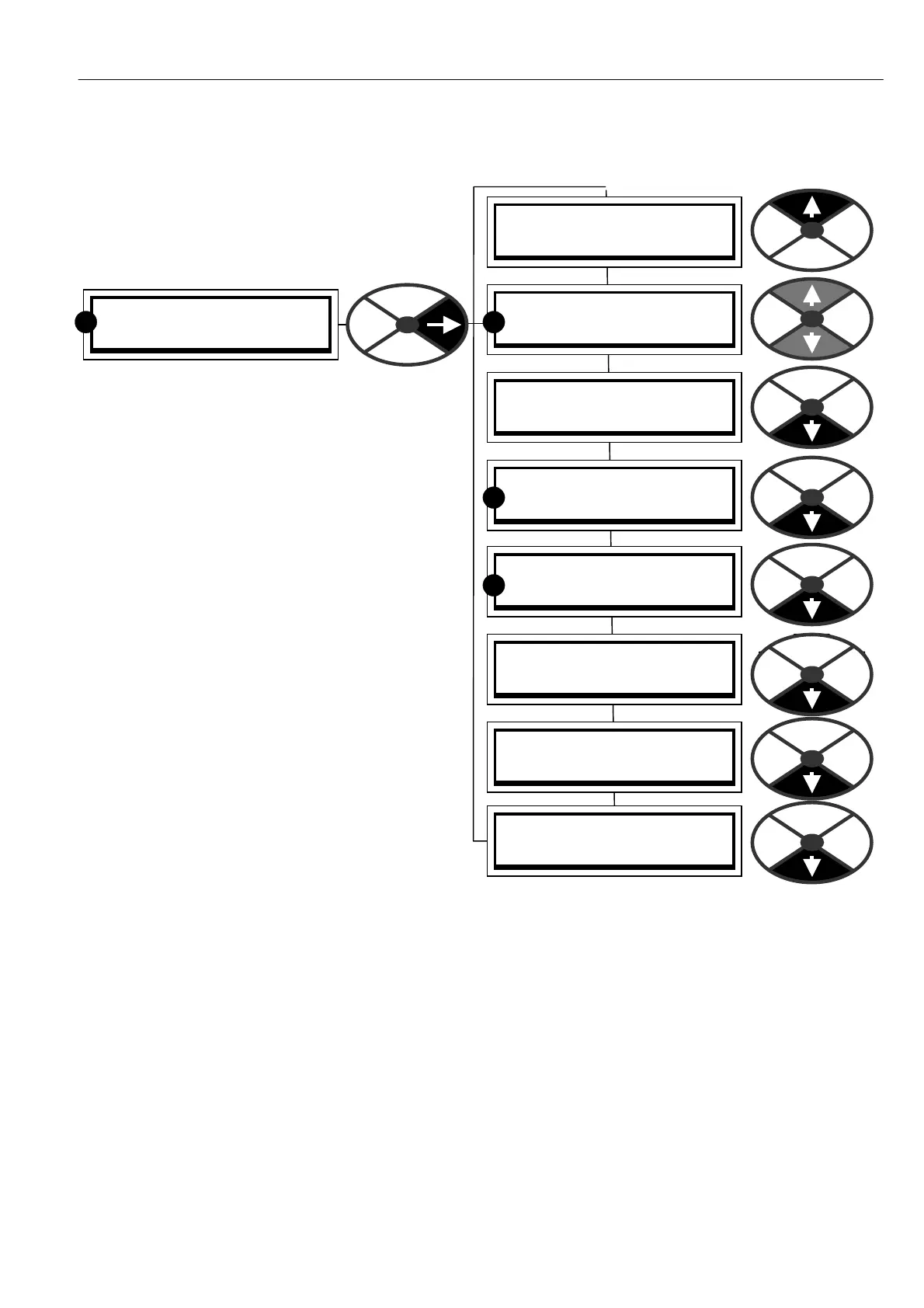
CH A NGE PARA METERS 2
ZERO INTERLO CKS 3
R
ZERO INTERLO CKS 3
SPINDLE ORIENT ATE 4
ZERO INTERLO CKS 3
115)STANDSTILL ENBL
ZERO INTERLO CKS 3
116)ZERO REF ST ART
ZERO INTERLO CKS 3
117)ZERO IN TLK SPD %
ZERO INTERLO CKS 3
118)ZERO INTLK CUR %
ZERO INTERLO CKS 3
119)A T ZERO REF FLA G
ZERO INTERLO CKS 3
120)A T ZERO SPD FLA G
R
R
R
ZERO INTERLO CKS 3
121)A T STANDSTILL