118 CHA NGE PARA METERS
6) If the position reference is non-zero, the shaft immediately seeks the position reference with respect to the
marker offset without waiting to stop at the marker offset position.
7) When the shaft reaches 242)POSITION REF target, 244)IN POSTION FLA G goes high.
8) If a new 242)POSITION REF is entered, the shaft immediately seeks the new 2 42)POSITIO N REF target.
9) When the shaft reaches the ne w 242)POSITION REF target, then 244)IN POSTION FLA G goes high again.
10) The sequence of 8 and 9 may be repeated as many times as desired as long as the speed demand
remains belo w 117)ZERO INTLK SPD %.
11) The speed demand rises above 117)ZERO INTLK SPD % and the block is turned off.
Note. Both 241)M ARKER OFFSET and/or 242)POSITION REF may be positive or negative, giving a choice of
clock/anti-clockwise search. This is used if the speed direction changes, and shaft reversal is undesirable.
To provide smoother stopping it may be helpful to use position references that include extra complete turns.
The block waits for approximately 40 0mS before activating to allo w undisturbed speed traverse through zero.
There are 2 hidden PINs which allo w access to the position counter (e.g. with serial link). PIN 71 0 gives a
running total. (4 counts per line in quadrature mode or 2 counts per line in single pulse train mode).
PIN 711 Is a decimal number input in the range 1 to 30,00 0 w hich is usually sent by a host computer. This is
used to divide the total position count so that the receiving host does not have to poll at a high rate.
6.10.9.2 SPINDLE ORIENT A TE / Zero speed lock PIN 122
Note, If this value is non-zero, AND both speed demand and feedback are less than 117)ZERO INTLCK SPD%
an encoder position control loop activates. The motor must have a bi-directional output shaft encoder.
(Quadrature OR pulse and direction). When locked, the speed may exceed 117)ZERO INTLCK SPD % without
losing the lock. Lock is only released by speed demand > 117)ZERO INTLCK SPD%.
Suggested value 10.00. Increasing improves positi on response, excessive gain may cause position instability.
See 6.1.9 C ALIBRATIO N / Speed feedback type PIN 9 QUICK START.
Warning. PL PILOT may add up to 10mS to PL/X cycle times, w hich may affect the response of applications
that require fast sampling. Eg SPINDLE ORIENT A TE. To overcome this effect, reduce the PL PILOT baud rate.
6.10.9.3 SPINDLE ORIENT A TE / Marker enable PIN 240
DISABLED turns off the spindle orientate function and the marker frequency monitor function.
Note, 122)ZERO SPEED LOCK function will continue to w ork however stopping position is arbitary.
6.10.9.3.1 Marker specification
The logic threshold levels for T15 ar 0 < 2 V, 1 > 4V. The maximum input voltage is 50V.
The minimum width specification for the marker is 10 uS.
The precise point of reference is the rising edge of the marker. Various types of marker signal may be used
with the system, but some types are less prone to noise than others.
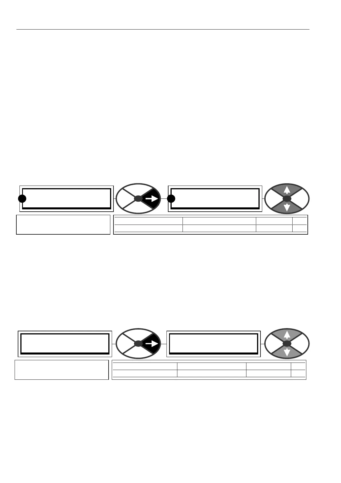
SPINDLE ORIENT ATE 4
240)M ARKER EN ABLE
240)M ARKER EN ABLE
DISABLED
PARA METER RANGE DEFAULT PIN
M ARKER ENABLE ENABLED or DIS ABLED DIS ABLED 240
Enables the marker in order to
determine spindle orientation.
SPINDLE ORIENT ATE 4
122)ZERO SPEED LO CK
122)ZERO SPEED LO CK
0.00
PARA METER RANGE DEF AULT PIN
ZERO SPEED LOCK 0.00 to 100.0 0 0.00 122
Sets the position control gain
for zero speed shaft lock.
R R