20 Introduction and Technical Data
3.1 Introduction
The PL/X DC motor controller uses closed loop control of armature current and feedback voltage to
give precise control of motor torque and speed. The unit also controls the motor excitation field. The closed
loop parameters are programmable by the user and a wealth of inputs and outputs are provided to allow very
complex motion control processes to be achieved. The series is comprised of 5 frame variants each with 2
and 4 quadrant models. Selected 2 quadrant models also offe r a unique regenerative stopping facility.
Plea se also refer to Part 3 PL/X 275-980 for extra details of frame 4 and 5 high power drives.
Programming the unit is designed to be simple. A large backlit alphanumeric display guides the user through a
friendly menu structure to select options and parameter changes. Built in application soft w are blocks are
provided to be connected up as desi red. Comprehensive fault monitoring and serial communications allo w off
site programming and remote diagnostics. All models are stock items. These units are very compact. The
savings made possible in panel space and enclosure costs may be significant.
3.2 How do they work?
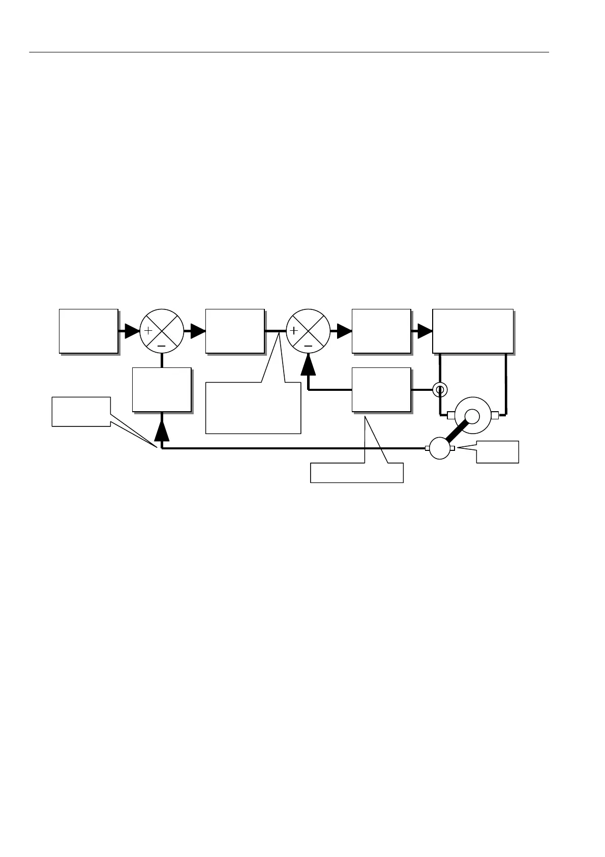
This shows the basic arrangement of the drive control loops. The 3-phase thyristor bridge is a phase-
controlled rectifier, which delivers po w er to the motor armature. The armature current (and hence the motor
torque) is sensed to provide feedback to the inner current loop. After being scaled this is compared to the
current demand. The current error amplifier is able to detect any difference, and then act in such a w ay that
the current feedback remains identical to the current demand during normal operation. This inner loop
monitors the armature current and delivers more current or less current as required.
The outer speed loop works in the same way as the inner current loop but uses different parameters. In the
above example, the demand is provided by the user in the form of a speed reference, and the speed feedback
is derived from a shaft-mounted tachometer. Any difference is detected and translated into a ne w current
demand level. This level provides the right amount of current (and hence torque) to reduce the speed error to
zero. This ne w demand level is presented to the inner current loop, which obeys as rapidly as possible.
The w hole process is performed on a continuous basis giving superb speed accuracy and dynamic
performance. In typical systems, there are numerous house keeping tasks and interface requirements. For
these, the PL/X series has a wealth of standard features to benefit the user.
A range of standard application blocks is included, with a user-friendly configuration facility that displays a
description of the selected connection points. The programming menu is designed for rapid travel to the
desired parameter using 4 keys and a large backlit alphanumeric display. A large number of monitoring
facilities is available to enable display of all points in the block diagram.
The unit is supplied with PL PILOT, a superb PC windo ws based configuration and monitoring tool.
(Note. Also available is the PLA, with applications blocks, I/O modules and comms facilities only)
Inner current loop
Speed
reference
from user
Current
error
amplifier
Speed
error
amplifier
Current
feedback
scaling
Speed
feedback
scaling
Firing circuit and
3-phase bridge.
A C in, DC out.
M
Tacho
The signal here
represents armature
current demand.
Outer
speed loop