CHA NGE PARA METERS 119
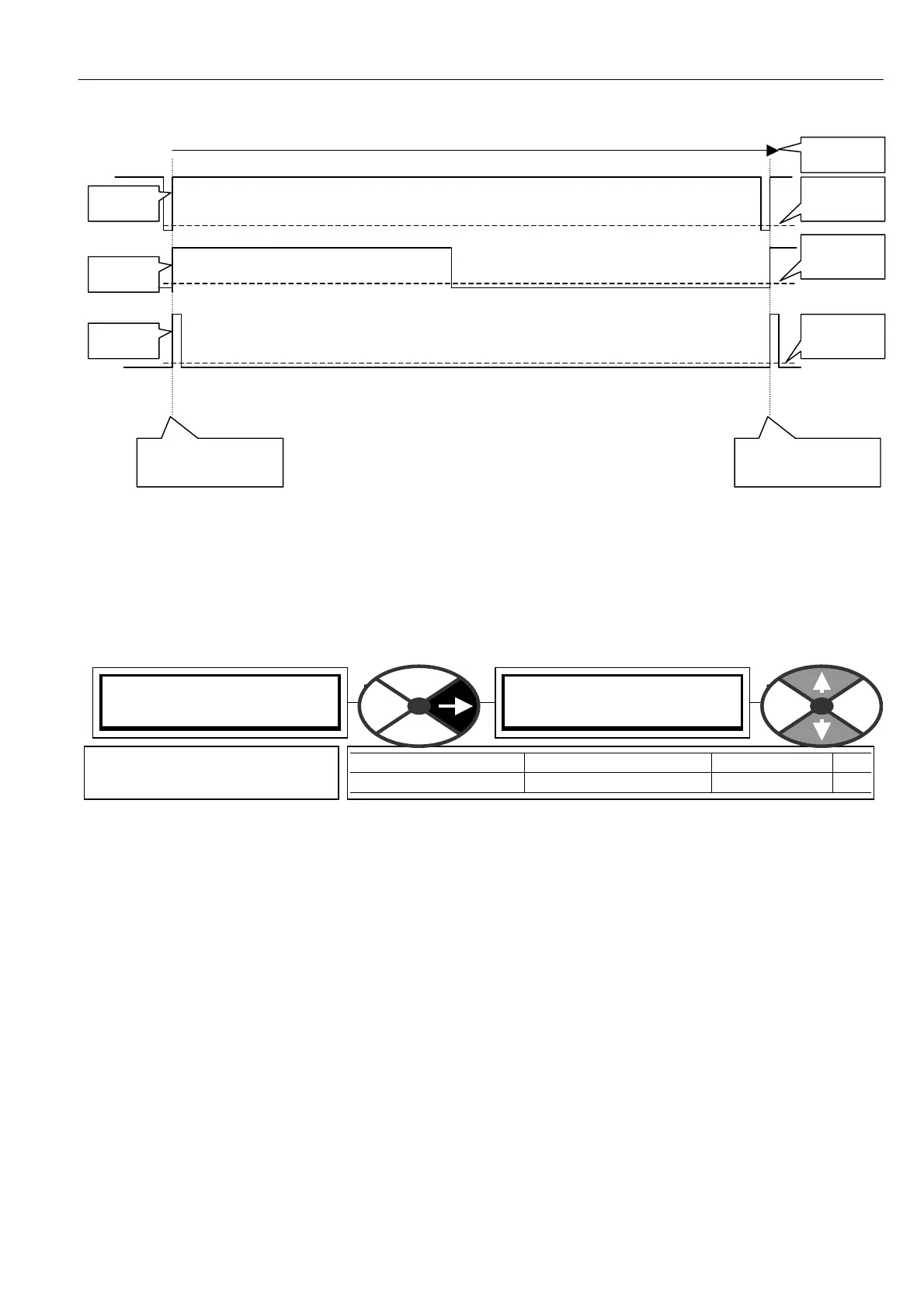
Type 1 is the preferred marker signal. This is because for most of the time the signal is well a w ay from the
logic threshold and noise is very unlikely to cause a false marker reading.
Types 2 and 3 how ever spend significant time near the logic threshold level, and therefore noise is more
likely to produce a false marker reading.
6.10.9.4 SPINDLE ORIENTATE / Marker offset PIN 241
Note. This offset is only added once at the commencement of orientation. It may be changed prior to the
next orientation sequence without affecting the existing position. The sign of the offset determines the
rotation direction w hen seeking the offset.
The count value needed for any offset angle depends on the resolution of the feedback encoder and the type
of encoder output. Quadrature encoders provide 4 counts per line. Single pulse and direction encoders
provide 2 counts per line.
E.g. Encoder has 3600 lines. Encoder type is QUA DRA TURE.
This gives 3600 X 4 counts per rev = 14400. That is 1440 0/360 = 40 counts per degree of displacement.
Hence if offset required is 56.8 degrees. Then enter counts of 56.8 X 40 = 2272.
E.g. Encoder has 2048 lines. Encoder type is SINGLE LINE PLUS DIRECTION.
This gives 2048 X 2 counts per rev = 4096. That is 4096/360 = 11.378 counts per degree of displacement.
Hence if offset required is 56.8 degrees. Then enter counts of 56.8 X 11.378 = 646.
If the encoder is mounted on the motor shaft, but the spindle that requires orientation is connected to the
motor via a gearbox such that the motor shaft and hence encoder is rotating faster than the spindle. Then
the number of counts per rev of the spindle will be increased by a factor equal to the gear box ratio.
Type 3
1 rev
Point of position
measurement
Point of position
measurement
Type 2
Type 1
Logic
Threshold
Logic
Threshold
Logic
Threshold
SPINDLE ORIENT ATE 4
241)M ARKER OFFSET
241)M ARKER OFFSET
0
PARA METER RANGE DEFAULT PIN
M ARKER OFFSET + /- 15,000 Counts 0 241
Used to offset an arbitrary
marker to a defined position.