40 Basic application
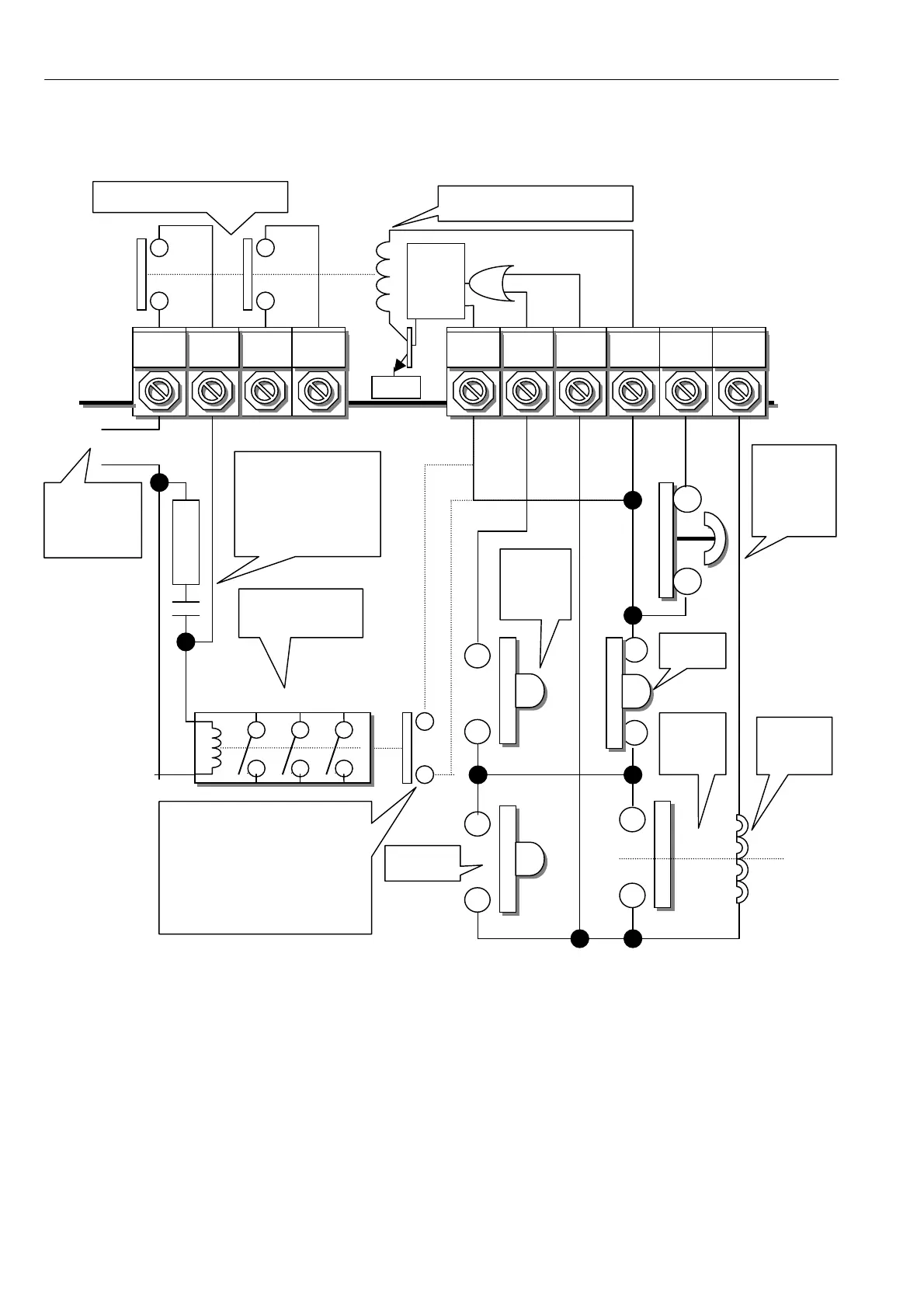
4.3.5 Using pushbuttons for STOP / START (With ramp to stop, jog and slack take up)
Note. This circuit will cause the ST OP MODE RA MP to operate w hen the STOP button opens during running.
Then the speed will ramp down under control of the ST OP M ODE RA MP. The main contactor will de-energise
after the ST OP MODE RA MP parameters have been satisfied.
See 6.5.1.3 Contactor drop out.
Note. The CSTOP must be high for at least 50mS prior to START going high.
The PLX, or PL models that have the regenerative stopping facility, will regenerate to maintain the ramp rate.
The JOG button operates as a JOG function w hen the drive is stopped (ST ART open), and as the SLA CK 1
take-up function w hen the drive is running (ST ART closed).
With the STOP button held open, no running button is operative. (JOG / SLA CK or ST ART)
T47
LA T1
T34
C STOP
T33
START
T35
+ 24V
T46
CO N2
T45
CO N1
Contactor
COIL
SUPPLY
CO AST
ST OP.
Must be
high prior
to ST ART.
M AIN
CONT A CTOR
INTERN AL C ONTA CTS
Internal contacts + 24V coil energised
by (START or J OG) AND CSTOP
0V
T36
0 V
T32
J O G
T31
RUN
T48
LA T2
Auxiliary contact on main
contactor in series with
RUN for contactors with
ON delay > 75mS.
(RUN must be at + 24V
to enable current)
RC SNUBBER across
contactor coil..
Typical values are
100 Ohms 1 W and
0.1uF both rated for
the coil supply volts.
STOP
ST ART
24 V
relay
Relay
COIL
JOG
Or
Slack
Stop mode
ramp delay.
Terminated
by RUN
going LO W