82 CHA NGE PARA METERS
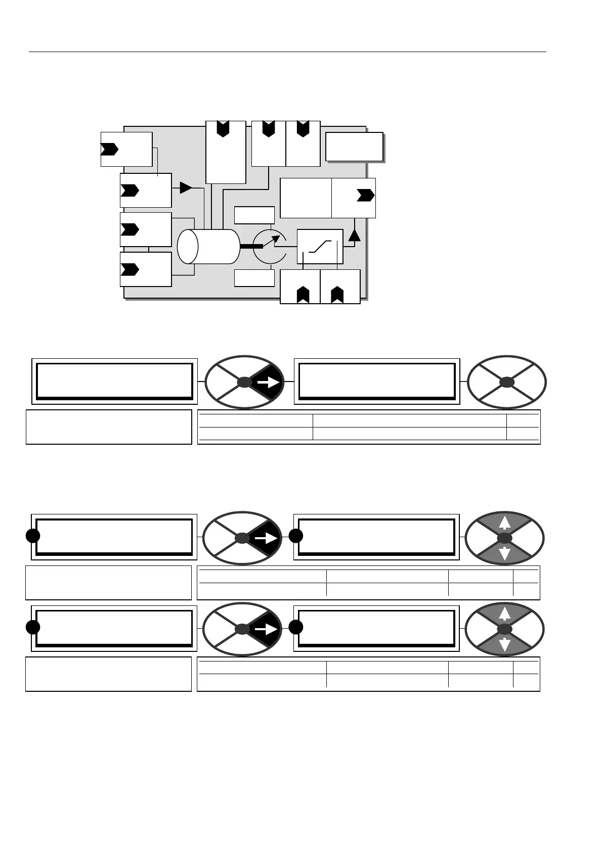
6.4.1 MOT ORISED PO T RA MP / Block diagram
6.4.2 MOT ORISED PO T RA MP / MP output monitor PIN 45
Default connection to speed reference summer. See 6.6.2 SPEED REF SUM MER / Internal speed reference 1
PIN 62.
6.4.3 MOT ORISED PO T RA MP / MP Up / Do wn time PINs 46 / 47
MO T ORISED
PO T RA MP
Up
time
PIN
4
PIN 50
PIN 51
PIN 4 9
Dow n
C ommand
Default T 9
Max clamp
PIN 50
Memory
boot up
1) Preset
(disabled)
2) Retain
(enabled)
Motorised
Pot
Output
PIN 45
PIN 4 8
Up
C ommand
Default T 8
Min clamp
PIN 51
+ 30 0 %
-3 00%
Motorised
potentiometer
GO T O
Do w n
time
PIN
47
PIN 5 2
Preset
Enable
Default T 7
PIN 5 3
Preset
Value
MO T ORISED PO T RA MP 3
46)MP UP TIME
46)MP UP TIME
10.0 SECS
PARA METER RANGE DEFAULT PIN
MP UP TIME 0.1 to 600.0 10.0 secs 46
Sets the ramp time for 100%
clockwise ( + ve) rotation.
MO T ORISED PO T RA MP 3
47)MP DO WN TIME
47)MP DO WN TIME
10.0 SECS
PARA METER RANGE DEFAULT PIN
MP DO W N TIME 0.1 to 600.0 10.0 secs 47
Sets the ramp time for -100%
anticlock wise (-ve) rotation.
R R
RR
R
MO T ORISED PO T RA MP 3
45)MP OP MONIT OR
45)MP OP MONIT OR
0.00 %
PARA METER RANGE PIN
MP OP M ONITOR + /-300.00 % 45
Allo ws the output value of the
motorized pot to be monitored.