24 Introduction and Technical Data
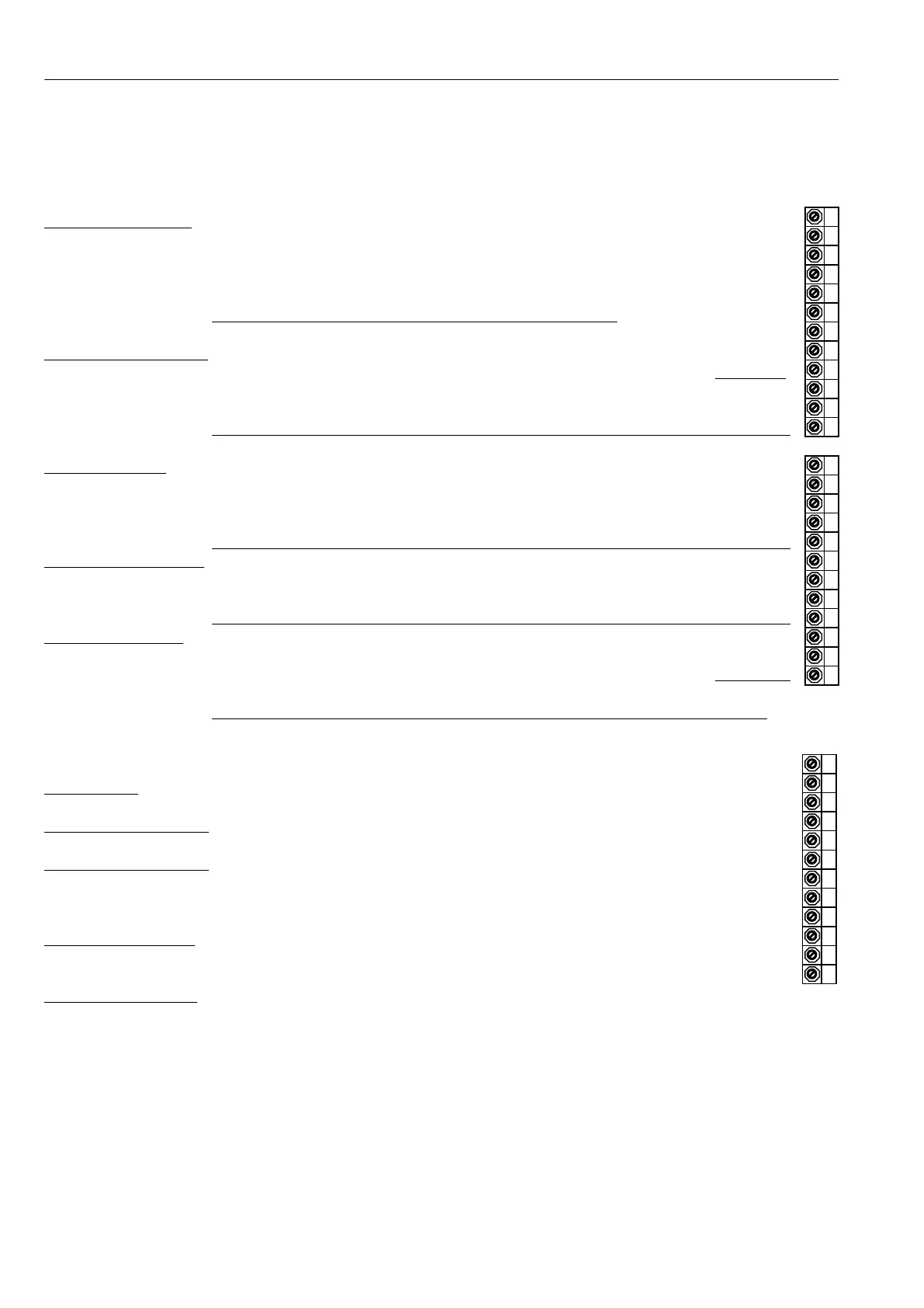
3.3.3 Control terminals electrical specification
This describes the electrical spec. of the control terminals. The function that each terminal has may depend
on the programmed choice of the user. The units are shipped with a set of default terminal functions, which
are described later. Although the function of the terminal may change its electrical specification does not.
UNIVERS AL INPUTS
8 analogue inputs with up to 5mV + sign resolution ( + /- 0.4 %) 0V 1
4 input voltage ranges + /-5/10/20/30 V on each input UIP2 2
UIP2 – UIP9 8 digital inputs with settable thresholds. Good noise immunity. UIP3 3
Overvoltage protected to + /-50V UIP4 4
Input impedance 100K for input scaling at 5 and 10 V range UIP5 5
Input impedance 50K for input scaling above 10V range
UIP6 6
UIP7 7
ANALOGUE OUTPUTS
4 analogue outputs ( + /- 0.4%) UIP8 8
3 programmable, 1 committed to output armature current signal UIP9 9
AOP1 AOP2 AOP3 2.5mV plus sign resolution A OP1 10
and IARM on T29 Short circuit protection to 0 V. Output current + /-5mA maximum A OP2 11
Output range 0 to + /-11 V. A OP3 12
DIGIT AL INPUTS
4 digital inputs 0V 13
Logic low below 2V, Logi c high above 4V. Low noise immunity. DIP1 14
DIP1 - DIP4 O vervoltage protection to + 50 V. Input impedance 10K Ohms DIP2 15
DIP3 and DIP4 may a lso be used for enc oder quadrature signals DIP3 16
See sections 3.4.2.1, 6.1.9 and 6.1.10 for encoder information DIP4 17
DIGIT AL IN/OUTPUTS
4 digital inputs. Also programmable as outputs (see digital outputs) DIO1 18
Logic low below 6V. Logi c high above 16V. DIO2 19
DIO1 – DIO4 Overvoltage protection to + 50 V. Input impedance 10K Ohms DIO3 20
When used as digital outputs the spec. is the same as D OP1-3 DIO4 21
DIGIT AL OU TPUTS
3 outputs (for 4 more outputs with this spec. use DIO1/2/3/4) DOP1 22
Short circuit protected. (Range 22 to 32 Volts for OP high) D OP2 23
DOP1 – DOP3 Over-temperature and over-voltage protected to + 50V DOP3 24
Each output can deliver up to 350m A. Total for all outputs of 350m A,
This spec. also applies to DIO1/2/3/4 when they are programmed as outputs
This connector is devoted to essentially fixed function controls 0V 25
T A CH INPUT
+ /- 200 V range Input impedance 150K Ohms T A CH 26
+ 10 27
REFEREN CE OUTPUTS
+ /-10.0 0V, 0.5%, 1 0mA max. Short circuit protection to 0V. -10 28
IARM 29
ARM A TURE CURRENT
+ /-5V linear output for + /-100 % mode l rating current. THM 30
Output current capability 10mA max. Short circuit protection to 0 V. RUN 31
IARM Programmable Uni-polar or Bi-polar output mode (tolerance + /-5%). JO G 32
ST ART 33
THERMISTOR INPUT
Motor temperature thermistor. If unused then connect to 0 V. CSTOP 34
THM OK < 200 Ohms, Overtemp > 2K Ohms. Connect from THM to 0 V + 24 V 35
0 V 36
CONT A CTOR control
24 V Logic inputs. Logic low below 6V, l ogic high above 16V
Input impedance. 10K Ohms. Overvoltage protection to + 50V
RUN Drive enable. Electronic enable for current loop and contactor drop out delays
JOG Jog input with programmable contactor drop out delay
START Start/stop. Drops contactor out at zero speed.
The drive will not start unless all alarms are clear. The drive will not restart after alarm induced contactor
drop out, unless START is removed for at least 50mS and re-applied.
CSTOP Coast stop. Drops contactor out immediately (100ms). Input impedance 1 0K Ohms.
+ 24V + 24 V output for external logic (Range 22 to 32 Volts). Short circuit protected.
Overvoltage protection to + 50V. Shares total current capability of ‘Digital Outputs’ (350mA), plus extra
50m A of its own. Total maximum available 400m A.