174 CONFIGURA TION
13.3.1 UNIVERSAL INPUTS / Block diagram
13.3.1.1 UIPX SETUP / UIP(2) to (9) Input range PIN 3(2)0 to 3(9)0
The + /-5 V and + /-10 V ranges are the most accurate (0.4 %, typically 0.1%).
The + /-20V and + /-30 V ranges use resistor divider networks and the absolute accuracy is 4 %. Also, if the
same signal is used externally else where, then it is important that the source impedance of the signal
connected to the terminal is as lo w as possible. This is because as the PL/X scans the inputs, the input
impedance will vary bet ween 100K and 50K for these ranges. A source of signal with a high input impedance
will be affected by the change in input resistance. This will not affect the accuracy of the reading within the
PL/X, but may cause an external measurement by another instrument to vary. It is important to remember
this w hen commissioning, as readings at the control terminals with a voltmeter may show slight variations if
the source impedance is high. The 5V and 10V ranges are not affected by source impedance.
13.3.1.2 UIPX SETUP / UIP(2) to (9) Input offset PIN 3(2)1 to 3(9)1
Note. + /-100% alw ays represents a + /-10Volts offset independant of the selected range. So when the
range selected is either 5V, 20 V or 3 0V the offset addition remains at + /10 V for + /-1 00 %, and hence no
longer represents a true percentage of the range. Whereas for the default 10V input range the offset
percentage represents the volts and the true percentage.
E. g. for a 2V offset to a signal using the 30V range enter the value 20.00 %.
The offset is added or subtracted prior to the scaling function.
This offset does not affect the signal used for the digital threshold comparison.
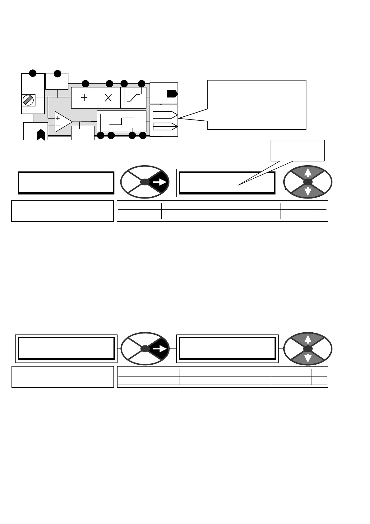
There are 2 independent
digital outputs driven by the
comparator.
Each has a G O TO connection
plus a value for high and a
value for lo w.
Range
PIN 32 0
T2
UIP2
Input
AN ALO G
GO TO
PIN 322
Scaler
PIN 321
Offset
PIN 325 / PIN 32 7
High
Low
PIN 326 / PIN 32 8
GO TO OP1
High value1
Low value1
High value2
Low value2
GO TO OP2
PIN 16 2
Dig mon
Threshold
PIN
32 9
PIN 323
PIN 324
Analog
monitor
PIN 15 0
UIP2 (T 2) SETUP 4
320)UIP2 IP RANGE
320)UIP2 IP RANGE
0
PARA METER RA NGE DEFA ULT PIN
UIP2 IP RANGE 1 = + /-5 V, 0 = + /-10V, 2 = + /-20V, 3 = + /-30V 0 = + /-10V 32
Sets the 0 to + /-100 % voltage
range of the UIPX input signal
This is a code,
not a voltage
UIP2 (T 2) SETUP 4
321)UIP2 IP OFFSET
321)UIP2 IP OFFSET
0.00%
PARA METER RA NGE DEFAULT PIN
UIP2 IP OFFSET + /- 100.0 0% 0.00 % 321
Sets the level of bi-polar offset
to be added to the input signal