CHA NGE PARA METERS 69
6.1.14 C ALIBRA TION / Analog tacho trim PIN 17
This trim factor may be applied during drive running. The factor is al ways greater than unity hence can only
increase the strength of the feedback. The closed loop system then receives feedback that is too high and
causes a reduction of the tacho voltage feedback and hence a reduction in speed. (This trim is useful if the
precise 8)M A X T A CH O V OLTS calibration parameter is not exactly kno wn and must be discovered during
running by starting with a higher than expected value. Once the correct level of feedback has been
determined using this trim, (monitor actual levels of feedback in the DIAGNOSTICS menu) it can then be
entered in the 8)MA X T A CHO V OLTS calibration parameter and this trim returned to 1.000).
6.1.15 C ALIBRA TION / Rated armature volts PIN 18 Q UIC K ST ART
Note. This must not exceed the maximum rated armature volts defined on the motor dataplate.
The armature volts is approximately proportional to the motor speed.
Example. A motor rated at 400 volts, 2000 rpm, is required to run at a maximum speed of 1000 rpm.
Therefore 200 volts will be the rated armature volts at 1000 rpm. This represents 1 00 % speed. Note. At lo w
speeds be a ware of heat dissipation in the motor at full torque. Use force venting of the motor if necessary.
If desired maximum rpm is higher than the base rpm then implement field w eakening in the CH ANGE
PARA METERS / FIELD CONTROL menu. You must howeve r verify that your motor and load are rated for
rotation above base speed. Failure to do so may result in mechanical failure with disastrous consequences. In
this mode the rated armature volts is usually set to the dataplate value in order to fully exploit the motor
ratings. Further speed increase is provided by field weakening and hence the armature voltage remains
clamped at the max rated value. This is referred to in the Field weakening menu as the spillover voltage.
6.1.16 C ALIBRA TION / EL1/2/3 rated AC volts PIN 19 QUICK ST ART
Note the actual A C volts may be monitored. See 7.7 DIA GNOSTICS / EL1/2/3 RMS M ON PIN 169.
The SUPPLY PH A SE LOSS alarm uses this parameter to determine the alarm threshold. The loss detection
threshold is set at approximately 75 % of the voltage entered here. By entering a voltage higher or lower than
the rated voltage it is possible to accomodate systems requiring detection at higher or lower thresholds.
Eg.
With 19)EL1/2/3 RA TED A C set to 415V the alarm will detect at 311 volts on EL1/2/3. (75% of 41 5 = 311)
With 19)EL1/2/3 RA TED A C set to 500V the alarm will detect at 375 volts on EL1/2/3. (75% of 50 0 = 375)
See 8.1.11.11 DRIVE TRIP MESSAGE / Supply phase loss, also see 3.6 Supply loss shutdo wn.
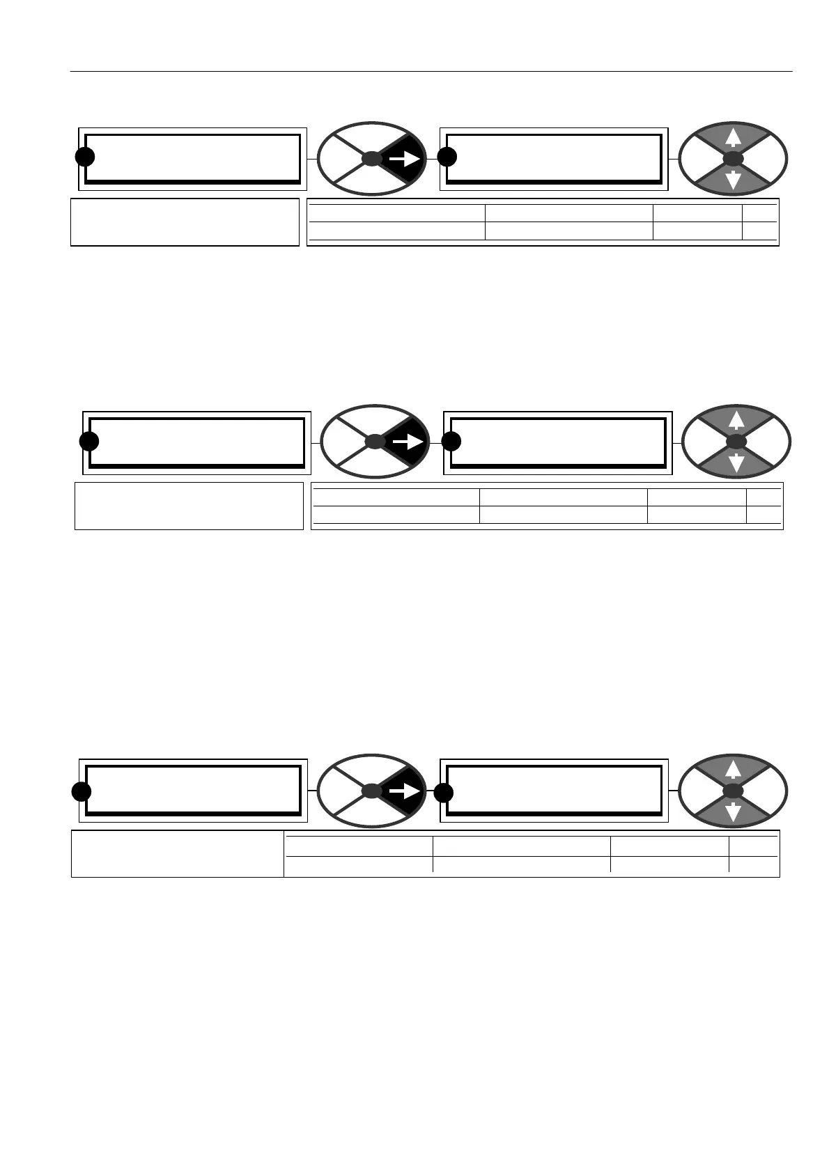
C ALIBRA TIO N 3
17)ANALO G T A CH O TRIM
17)ANALO G T A CH O TRIM
1.0000
PARA METER RANGE DEFAULT PIN
ANALO G TA CH O TRIM 1.0000 to 1.1000 1.0000 17
Sets a positive trim factor for
the analog tacho feedback
RR
C ALIBRA TIO N 3
18)RA TED ARM V OLTS
18)RA TED ARM V OLTS
460.0 V DC
PARA METER RANGE DEFAULT PIN
RA TED ARM V OLTS 0.0 to 100 0.0 V OLTS 460.0 V DC 18
Sets the desired max armature
voltage at 100% speed
R R
C ALIBRA TIO N 3
19)EL1/2/3 RATED A C
19)EL1/2/3 RATED A C
415.0 V OLTS
Enter the 3 phase A C supply
volts connected to EL1/2/3.
PARA METER RANGE DEFAULT PIN
EL1/2/3 RA TED A C 0 to 1000.0 VOLTS 415.0 V OLTS 19
R
R