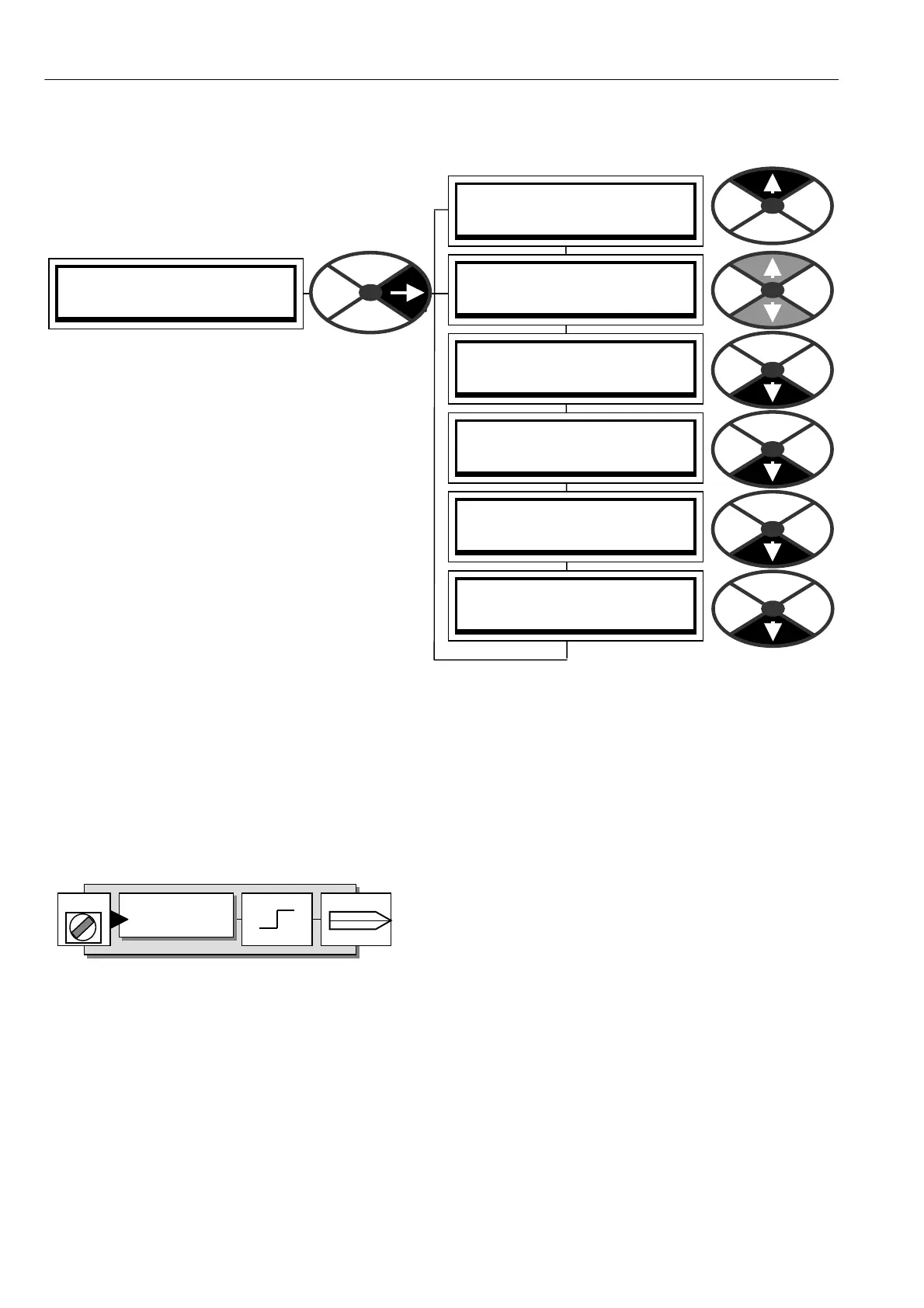
116 CHA NGE PARA METERS
ZERO INTERLO CKS 3
SPINDLE ORIENT ATE 4
SPINDLE ORIENT ATE 4
244)IN POSITION FLA G
SPINDLE ORIENT ATE 4
122)ZERO SPEED LO CK
SPINDLE ORIENT ATE 4
240)M ARKER EN ABLE
SPINDLE ORIENT ATE 4
241)M ARKER OFFSET
SPINDLE ORIENT ATE 4
242)POSITION REF
SPINDLE ORIENT ATE 4
243)M ARKER FREQ MO N
6.10.9 ZERO INTERLOCKS / SPINDLE ORIENTATE
PINS used 122 and 240 to 244
Note. It is only possible to use this function with
PLX models, and PL models with the regenerative
stopping facility. See 3.3.1.
This sub menu is used to provide spindle
orientation. It requires the mechanic al syste m to be
fitted with an incremental encoder with bi-
directional output to provide position feedback.
If the encoder has been selected for a speed
feedback option in the C ALIBRA TION menu then
that function is not disturbed by this block being
operational.
The spindle orientation will function irrespective of
the speed feedback type.
The block utilises the encoder marker to provide
the controller with the absolute position angle of
the encoder. The marker is input via terminal T 15.
PL models with the regenerative stopping facility can only orientate during the contactor drop out delay.
To maintain position lock during a contactor drop out delay ensure 6.5.4 STOP MODE RA MP / Live delay
mode PIN 58 is set to ENABLED. See also 6.5.6 ST OP MODE RA MP / Drop-out delay PIN 60.
The encoder pulses are input on terminals T16 and T17 (Note. Quadrature type encoders are recommended
because they will usually provide more accurate counting during reversals than Pulse and direction types).
Terminals T15, T16, T17 are also used as standard logic inputs. (DIP/2/3/4). This function continues to
operate. However logic levels that are changing at a frequency of greater than 20 Hz will not necessarily be
recognised by the standard logic input function. The standard logic input function can be useful to check
logic output levels of a slowly rotated encoder during commissioning.
The encoder input type and scaling is programmed by using
the C ALIBRA TION / EN CODER SC ALING menu to select the
encoder type, sign, encoder lines and rpm.
The SPINDLE ORIENT A TE block counts the pulses from the encoder in a bi-directional counter. It counts
forward or backward depending on rotation direction. This count represents the amount of angular rotation of
the encoder and hence the motor shaft. The position count is compared with the required spindle orientation
position reference to develop an error signal which is employed in a negative feedback loop in the drive. Thus
the motor will rotate in such a direction as to reduce the error to zero, and hence bring the encoder marker to
the spindle position reference.
The marker uniquely defines the absolute position of the rotating encoder to the machine. If 241)M ARKER
OFFSET and 242)POSITIO N REF are both zero, then the encoder shaft will be positioned at the marker.
How ever it is more than likely that the marker will be in an arbitrary position. To overcome this problem,
241)M ARKER OFFSET is provided to perform a one off positioning of the shaft to a know n position, every
time the spindle orientate is actioned. E. g. to top dead centre.
242)POSITION REF is then always referred to this kno wn position.
PIN X X X
PIN X X X
DIPX
Input terminal
T15/1 6/17
G O T O
High OP val
Low OP val