34 Basic application
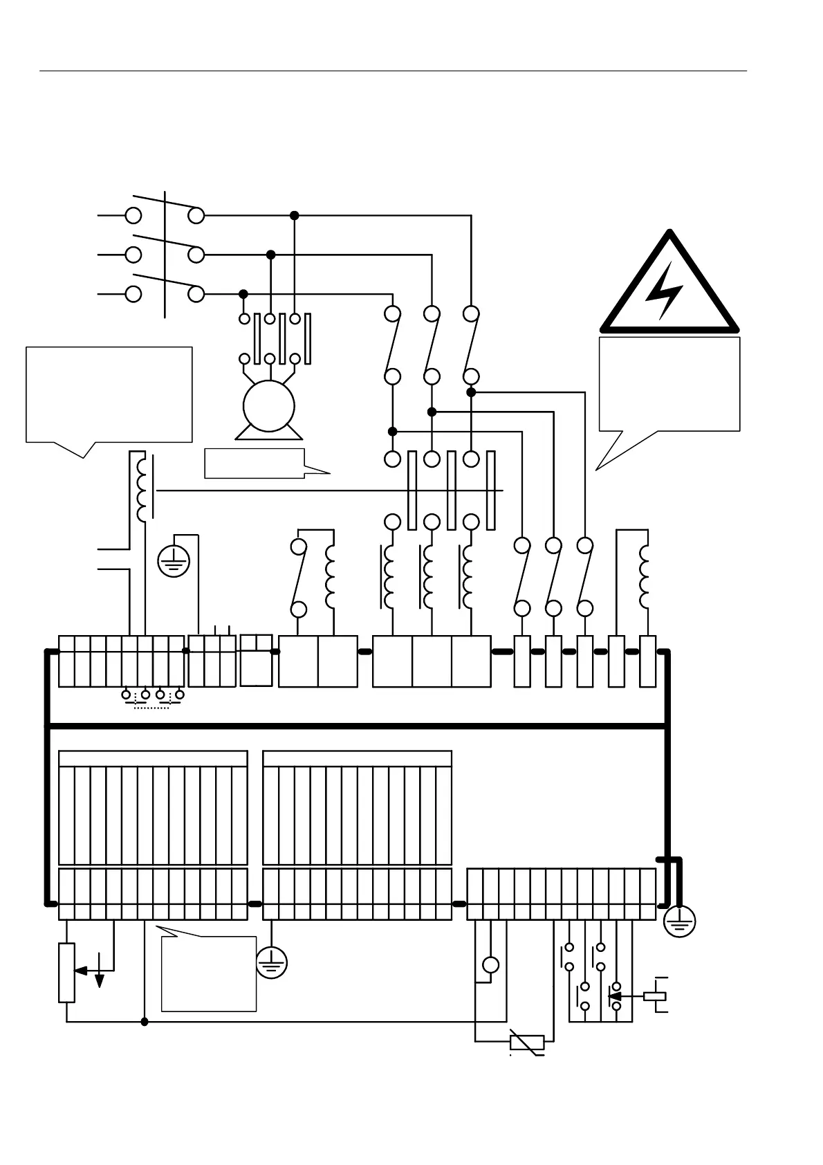
4.1 Basic speed or torque control
This section sho ws the essential requi rements for a very basic speed or torque control application.
Note that the arrangement of the contactor shown here allo ws continuous phase sensing on EL1/2/3.
VERY IMPORTANT see 4.2 Main Contactor operation, 4.3 Main contactor wiring options, 14 Installation.
Note. B1, B2 Fan supply is 110V AC 50VA for PL/X185-265 and 240V AC 100VA for PL/X 275-980.
1
0V
13
0 V
2 3 4 5 6 7 8 9
10 11 12
UIP2
UIP3
UIP4
UIP5
UIP6
UIP7
UIP8
A OP1
A OP2
A OP3
0V
DIP1
DIP2
DIP3
DIP4
14 15 16 17 18 19 20 21 22 23 24
DIO1
DIO2
DIO3
DIO4
DOP1
DOP2
DOP3
25 26 27 28 29 30 31 32 33 34 35 36
TA CH
+ 10
-10
IARM
THM
RUN
JOG
ST ART
CSTOP
+ 24V
0V
41 42 43 44 45 46
51 52 53
RA +
NC
RA-
CON1
EARTH
N
L
NC
CON2
A + A- L1 L2 L3
EL1
EL2
EL3
F-
F +
TERMIN ALS 1 -1 2 FUNC TIO N TERMIN ALS 13 -2 4 FUN CTIO N
110 V
A C IP
FAN
B1 B2
Terminals show n on the top edge are located on the lower level power board. (B1/B2 on top edge of 1 85/225/265 models)
Symbolic connection block.
Terminals 1 - 36 are located on the
bottom edge of the upper control
board arranged as 3 blocks of 12.
Terminals 2 -12, 14 - 24, and 31
are programmable.
Their default function is shown here.
Speed ref/Current ref
Ramped Speed Setpoint
Lower Current Clamp
Main/Upper Current Clamp
Motorised Pot Preset
Motorised Pot Increase
Motorised Pot decrease
Speed Feedback
0V Terminal
Total Speed Reference
Total Current Demand
Speed Reference
0V Terminal
Zero reference interlock
Jog Speed Select
Ramp Hold
Current Clamp Select
Spare input
Spare input
Feedback encoder
Feedback encoder
Zero Speed
Ramping flag
Drive Healthy
contactor
coil supply
110V A C
3 phase
motor
blower
circuit
breaker
main
semi-conductor
fuses
main
contactor
main
contactor
coil
Isolator
armature
field
line
reactor
auxiliary
semi-conductor
fuses
L3
L2
L1
10K
speed pot
cw
acw
emergency
stop relay
startjog
run
T
+
thermistor
UIP9
AC Control
Supply Inputs
(110 -240V)
Protective
clean earth.
Control supply
dirty earth
47 48
LA T1
LA T 2
Substantial
chassis
earth
Use DC semiconductor
fuse for
regen
applications
W ARNING. Do not
allow coil supply to be
externally interrupted.
Retro- fit relay logic is
often the main culprit.
W ARNING
The phase order
of EL1/2/3 must
be the same as
L1/2/3
For Torque control
enter Torque ref
into T6. (0 - 1 0 V).
For speed control
link T 6 to + 1 0V
on T 27.
A C 1 rated