48 Menu tree structure
SPD% Iarm Ifld RJSC
0 0 0 0000
R
Sref Ilim -Ilim mode
0 150 -150 0000
R
PRESS RIGHT KEY FOR
ENTRY MENU LEVEL 1
R
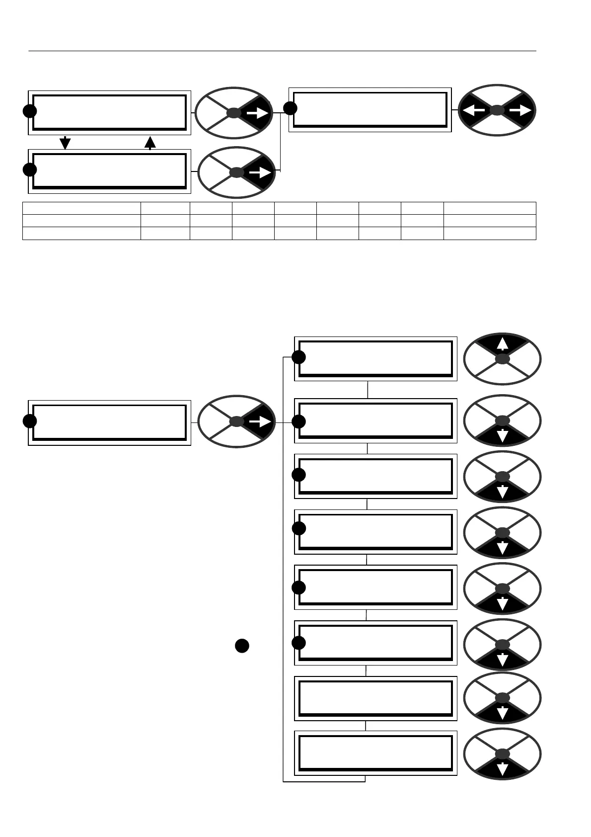
5.1.6 Default % DIA GN OSTIC summary windows
T wo default % DIA GNOSTIC windo ws toggle every
5 seconds. The linear parameters are integer %.
If toggling stops and mode = C ONF, then EN ABLE
G OT O GETFROM must be DISABLED. See 13.2.7.
Displayed mneumonic SPD% Iarm Ifld RJSC Sref Ilim -Ilim mode
Source PIN number 1 31 134 144 164 123 138 139 167 (ST OP/RUN)
Manual section 7.1.10 7.2.2 7.3.2 7.5.3 7.1.1 7.2.6 7.2.6 7.5.6
5.1.7 Finding the soft w are version number of the unit.
To find the version number of the soft ware loaded on the drive, see 11.4 DISPLAY FUN CTIO NS / Soft w are
version. This is a version 5.15 manual. Version 5.17 and above software has a ll the functions described.
Soft w are version 4.05 upwards is compatible with PL PILOT version 4.05. How ever PL Pilot (See 13.1.1 )
will not be able to utilise or configure FIELDBUS parameters. See also16.1 Record of modifications.
5.2 ENTRY MENU
When you enter the first vertical menu level (level 1)
you will find 8 headings as you scroll up and dow n.
After tapping the right key to proceed to the next
level, you can travel up and down the level using the
up and do wn keys. The menus are circular so you
can travel up or dow n to reach your desired
destination. The menus are designed so that the
most frequently used windows are closest to the
entry points.
There are 2 styles of menu that can be selected
using DISPLA Y FUNC TIONS.
REDUCED and FULL
The reduced menu shows only the commonly used
selections and enables more rapid travel around the
tree structure
If the display is sho wn in this manual with
next to it then this indicates that it is in
both the reduced AND the full menu.
Note. There are about 50 adjustable parameters in
the reduced menu. There is also a facility for storing
a second set of reduced menu parameters which can
be called into use using a digital input. See 6.1.17
C ALIBRA TIO N / Motor 1 or 2 select PIN 20
See also 11.5 Remotely mounted display unit.
R
PRESS RIGHT KEY FOR
ENTRY MENU LEVEL 1
R
ENTRY MENU LEVEL 1
PARA METER SA VE 2
ENTRY MENU LEVEL 1
CH A NGE PARA METERS 2
ENTRY MENU LEVEL 1
APPLIC A TION BLOCKS 2
ENTRY MENU LEVEL 1
DIA GNOSTICS 2
ENTRY MENU LEVEL 1
MO TOR DRIVE ALARMS 2
ENTRY MENU LEVEL 1
SERIAL LINKS 2
ENTRY MENU LEVEL 1
DISPLA Y FUNC TIONS 2
ENTRY MENU LEVEL 1
CONFIGURA TION 2
R
R
R
R
R
R