122 DIA GNOSTICS
SPEED LO OP MONITOR 3
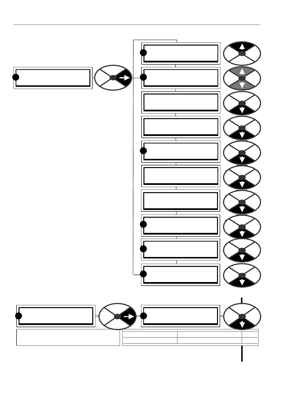
123)T OTAL SPD REF MN
123)T OTAL SPD REF MN
0.00%
PARA METER RANGE PIN
TO T AL SPD REF M N + /-300.00% 123
Shows the % value of the total speed
reference before the ST OP RA MP BLOCK.
R R
DIA GNOSTICS 2
SPEED LO OP MONITOR 3
SPEED LO OP MONITOR 3
131)SPEED FBK MON
SPEED LO OP MONITOR 3
123)T OTAL SPD REF MN
SPEED LO OP MONITOR 3
127)ARM V OLTS % MON
SPEED LO OP MONITOR 3
124)SPEED DEM A ND M O N
SPEED LO OP MONITOR 3
125)SPEED ERROR MON
SPEED LO OP MONITOR 3
126)ARM V OLTS M ON
SPEED LO OP MONITOR 3
128)BA CK EMF % MON
SPEED LO OP MONITOR 3
129)T A CHO V OLTS MO N
SPEED LO OP MONITOR 3
130)M OTOR RPM MON
R
R
R
R
R
R
SPEED LO OP MONITOR 3
132)ENCODER RPM MON
R
7 . 1 DIAGNOSTICS / SPEED LOOP
MONITOR
PIN number range 123 to 132
This menu allows monitoring of the parameters
associated with the the speed loop.
The feedback sources can also be read in
engineering units which alleviates the need to
undertake difficult readings with a voltmeter
during commissioning.
For convenience, the armature voltage is also
sho wn as a % of max rated value in a dedicated
windo w.
The armature volts, tacho volts and encoder rpm
monitors all function continuously, irrespective of
which is the source of feedback. These signal
channels may be utilised for tasks other than
speed feedback.
7.1.1 SPEED LOOP MONIT OR / Total speed reference monitor PIN 123
This parameter is a summation of all possible speed references including the RUN M ODE RA MP.
Note that the RUN MODE RAMP may be active when the unit is in stop mode. This feature allows
cascaded systems to function even if a member of the system is stopped. See 6.2 CH A NGE PARA METERS /
RUN MODE RAMPS.