DIA GNOSTICS 123
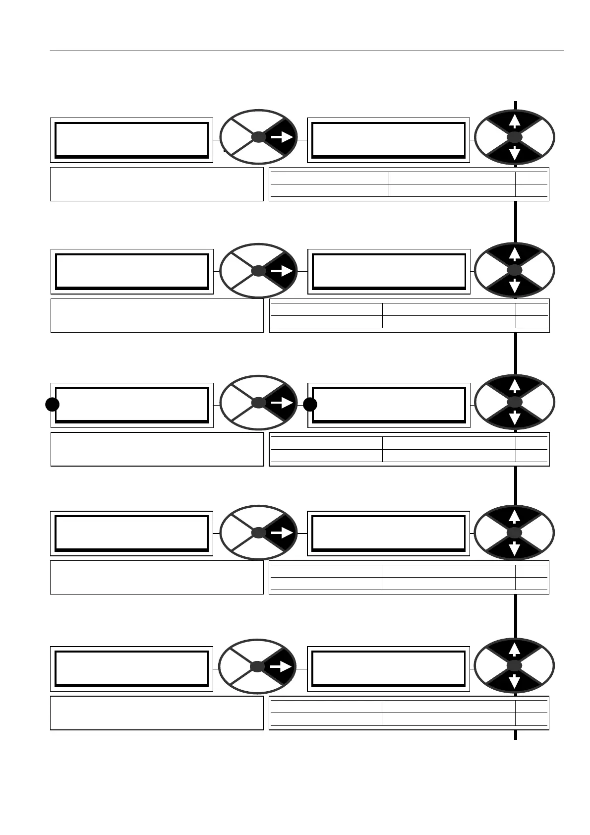
7.1.2 SPEED LO OP MONIT OR / Speed demand monitor PIN 12 4
7.1.3 SPEED LOOP MONIT OR / Speed error monitor PIN 125
7.1.4 SPEED LOOP MONIT OR / Armature volts monitor PIN 126
7.1.5 SPEED LOOP MONIT OR / Armature volts % monitor PIN 127
Note. The 100% level is equivalent to 18)RA TED ARM V OLTS
7.1.6 SPEED LOOP MONITOR / Back emf % monitor PIN 128
Note. Back EMF = A VF – IR drop
SPEED LO OP MONITOR 3
124)SPEED DEM A ND M O N
124)SPEED DEM A ND M O N
0.00%
PARA METER RANGE PIN
SPEED DEM AND M ON + /-3 00.00 % 124
Shows the % value of the total speed
demand after the STOP RA MP BLOCK
SPEED LO OP MONITOR 3
125)SPEED ERROR MON
125)SPEED ERROR MON
0.00 %
PARA METER RANGE PIN
SPEED ERROR MON + /-300.00% 125
Shows the value of the speed error as a
% of full scale.
SPEED LO OP MONITOR 3
126)ARM V OLTS M ON
126)ARM V OLTS M ON
0.0 Volts
PARA METER RANGE PIN
ARM V OLTS M ON + /- 1250.0 Volts 126
Shows the average DC armature voltage
independently of feedback type.
RR
SPEED LO OP MONITOR 3
127)ARM V OLTS % MON
127)ARM V OLTS % MON
0.00%
PARA METER RANGE PIN
ARM V OLTS % MON + /-300.00% 127
Shows the value of the average DC arm
voltage as a % of desired max arm volts.
SPEED LO OP MONITOR 3
128)BA CK EMF % MON
128)BA CK EMF % MON
0.00%
PARA METER RANGE PIN
BA CK EMF % MON + /-300.00% 128
Shows the value of the average D C back
emf as a % of the desired max back emf.