CHA NGE PARA METERS 61
6.1.3 C ALIBRA TION / Current limit (%) PIN 3 QUICK ST ART
This parameter may be adjusted w hilst the PL/X is running.
If a 150 % overload limit is too lo w for your application then it is possible to cater for larger overload
percentages on motors smaller than the PL/X model armature current rating.
See 6.8.3.1 CURRENT O VERLO AD / Overload % target PIN 82.
If the current exceeds the level set by the overload target, then after an appropriate d well time, it is
progressively reduced to the overload target level.
Table showing maximum overloads according to:- Full load motor current, as a % of 2)RA TED ARM AMPS.
Full load motor current
(82)O/LO A D % TARGET) as
a % of 2)RATED ARM A MPS
Maximum available Maximum overload % available.
(With respect to full load motor current)
100% 150% 150 / 100 = 150%
90% 150% 150 / 90 = 166 %
80% 150% 150 / 80 = 187 %
75% 150% 150 / 75 = 200 %
60% 150% 150 / 60 = 250 %
50% 150% 150 / 50 = 300 %
37.5 % 150% 150 / 3 7.5 = 400%
30% 150% 150 / 30 = 500 %
If 3)CURRENT LIMIT(%) or if 82)O/LO A D % T ARGET level is set to 0% then no permanent current will flo w.
See 6.8.3.1 CURRENT O VERLO AD / Overload % target PIN 82.
6.1.4 C ALIBRA TION / Rated field amps PIN 4 QUICK START
If the field amps is not given on the motor dataplate, you can deduce it by measuring the resistance of the
field winding after allowing it to reach full working temperature, then using the following equation
Field current = Field dataplate volts / Resistance in Ohms
Alternatively if you kno w the rated field voltage, you can go to the CH A NGE PARA METERS / FIELD
CONTROL menu, and select the 100)FIELD V OLTS OP % clamp parameter. Adjust the field output voltage to
the dataplate value, as a % of the applied A C supply. Please ensure that 4)RATED FIELD A MPS is sufficiently
high to force the 100)FIELD VOLTS OP % clamp into operation at the desired voltage under all conditions.
4)RA TED FIELD A MPS scaled by 114)FIELD REFERENCE sets the demand for the field current control loop.
and 100)FIELD V OLTS OP % operates as a clamp on the field bridge firing angle.
The one that results in the lo w er output, has priority.
Hence it is possible to operate with the field current control prevailing and the voltage % as a higher safety
clamp, or the voltage % clamp prevailing and the field current control as a higher safety level.
C ALIBRA TIO N 3
4)RA TED FIELD A MPS
4)RA TED FIELD A MPS
X X.XX A MPS
PARA METER RANGE DEF AULT PIN
RATED FIELD A MPS
0.1 A -100% of model rating
25 % A MPS 4
This is the desired 100 % DC
output field current in amps
R
R
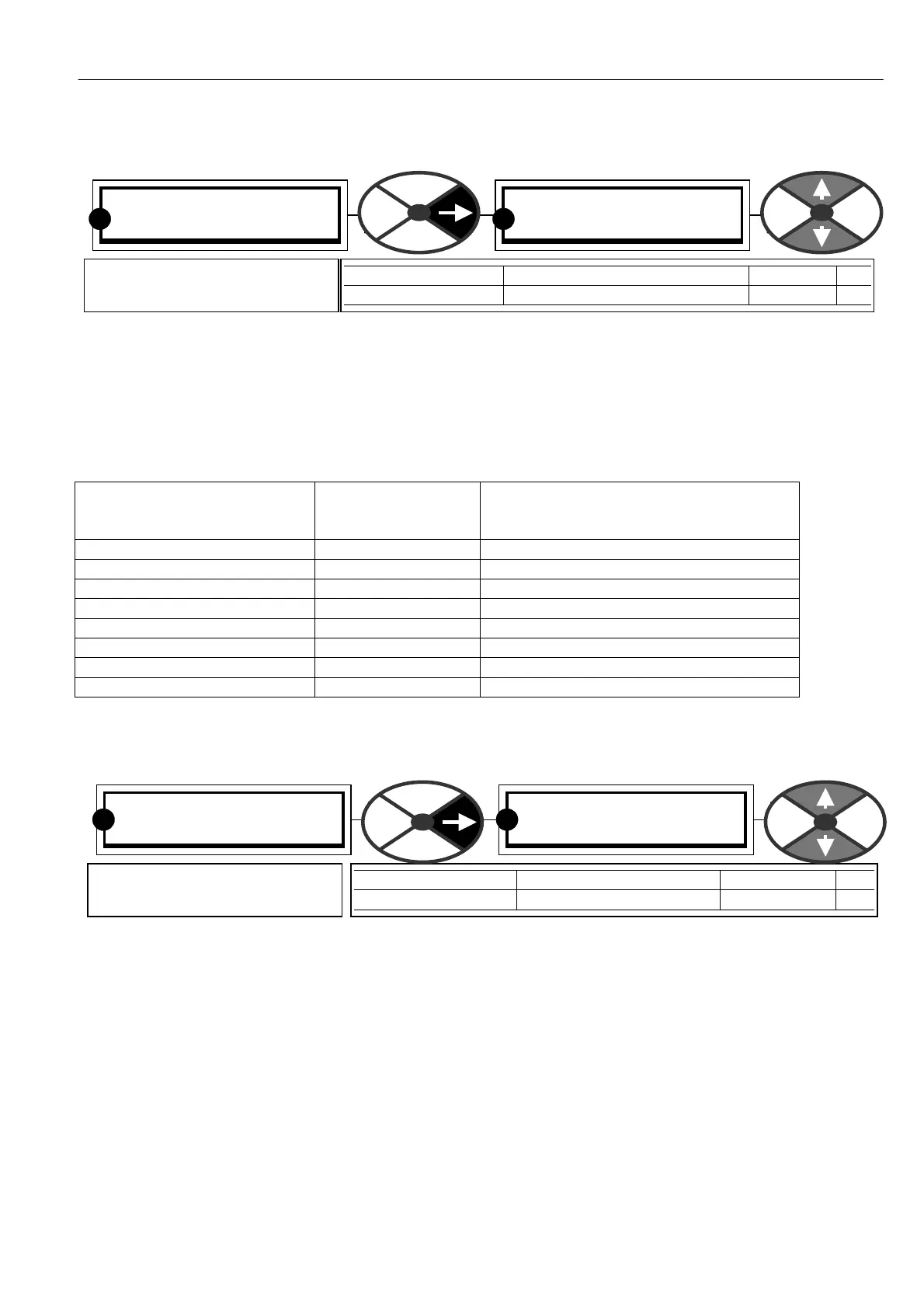
C ALIBRA TIO N 3
3)CURRENT LIMIT(%)
3)CURRENT LIMIT(%)
150.00 %
PARA METER RANGE DEF AULT PIN
CURRENT LIMIT(%) 0 to150 % of rated motor amps 150.00% 3
This is the desired current limit
% of 2)RATED ARM A MPS
R R