60 CHA NGE PARA METERS
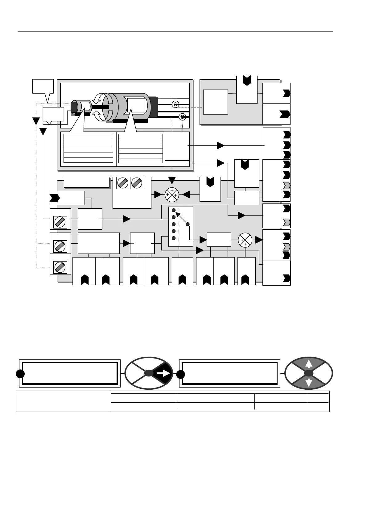
6.1.1 C ALIBRA TION / Block diagram
6.1.2 C ALIBRA TION / Rated armature amps PIN 2 QUICK ST ART
Note the presence of a PIN number on the bottom line sho ws that one more step right takes us to the end of
a branch.
Then we reach the end of a branch of the tree and this has resulted in a parameter value on the lo wer line
which can be modified by use of the up/do wn keys.
This current may be less than the value on the motor data-plate, but must not normally be higher.
(However, see also 6.8.3.1.2 How to get overloads greater than 150% using 82)O/LO A D % T ARGET).
See 13.13.4 DRIVE PERSONALITY / Armature current burden resistance PIN 680
PIN 12 6
A V mon
PIN 12 7
A V % mon
PIN 12 8
Bemf %
C ALIBRA TIO N 3
2)RA TED ARM A MPS
2)RA TED ARM A MPS
X X X . X A M P S
The desired 100% continuous
rated motor current in amps
PARA METER RANGE DEFAULT PIN
RA TED ARM AMPS 33 -100 % of PL/X ratin
(33 %)X X X.X A 2
R
R
DC shunt wound motor
Tachogenerator
And/or encoder
F + /F-
A + / A-_
Data
Plate
MO TOR DA T APLA TE
Max rated arm amps
Max rated arm volts
Max rated field amps
Max rated field volts
Base rated RPM
TA CH O D AT APLA TE
Volts / 1000 RPM
Type:Bipolar/Rectified/A C/DC
EN CODER D A T APL A TE
Lines per revolution
Isolated
sensors
for arm
current
and PL/X
A + / A-
terminal V
Av
IA
Rated
field
Amps
PIN 4
PIN 144
Field
Amps
Feedback
PIN 143
Field
Amps %
Feedback
Internal
isolated
sensors
for field
current
Max Tacho
Volts PIN 8
T 2 6
Input pulse sign
detector and freq
measurement
Arm Cur fb
mon A MPS
PIN 13 5
% PIN 1 34
Unfiltered
% PIN 7 19
DC Kw atts
PIN 17 0
+ /-
and
X
Quadrature
enable
PIN 10
T17 A
T16 B
Speed
Fb
Type
PIN 9
Encoder
lines
PIN 11
Mot/Enc
Speed
Ratio
PIN 12
Encoder
sign
PIN 13
X
Base
rated
RPM
PIN 5
Desired
M AX
RPM
PIN 6
X
Zero
speed
offset
PIN 7
Rated
Armature
Amps
PIN 2
IR
comp
PIN 14
PIN 132
Encoder
Rpm
Monitor.
Unfiltered
T4 1 T43
A V sensing inputs
only used with DC
side contactors
C ALIBRA TION
X
Encoder
pulses
Tacho
voltage
PIN 131
Speed Fb
Monitor.
Unfiltered
PIN 71 5
(RPM Pins
13 0/71 7
PIN 129
Tacho Volts.
Unfiltered %
Tacho mon
PIN 71 6