CHA NGE PARA METERS 99
6.8.3.1 CURRENT O VERLO A D / Overload % target PIN 82
This CURRENT O VERLO A D menu allows the final current % target limit to be set by this parameter.
This would normally be the ful l load current of the motor.
Having the facility to set this parameter independantly of 2)RA TED ARM AMPS allows further flexibility.
This block allows the load current to span up to 150% of 2)RA TED ARM A MPS. (If any other lower limits are
prevailing they will of course determine the current limit). See 6.8.1 CURRENT C ONTROL / Block diagram.
An internal integrator, with a finite capacity, fills up when the armature current exceeds PIN 82, it empties
for armature current less than PIN 82. The unused capacity of the integrator determines the time remaining,
before automatic reduction of the current limit commences. A 150% limit is available until the integrator
becomes full. Then the current limit is linearly reduced in this block from 150% towards PIN 82.
Note. The limit reduction alw ays starts from 150% and ramps do wn tow ards 82)O/LO AD % T ARGET.
See 6.8.3.2 CURRENT O VERLO A D / Overload ramp time PIN 83.
If the load continues to require current in excess of PIN 82 level then it will remain limited to PIN 82 level.
(N OTE this implies the speed loop is not getting the current it demands and hence there will be speed error).
If the load subsequently falls beneath PIN 82 level, then the internal integrator starts to de-integrate back to
its empty state. (Ready for next overload). The overload available will start increasing.
However full de-integration is required before the full overload capacity is once more available.
Note. For small overloads the time prior to limit reduction can be very long, but the integrator is still filling up.
Hence after a long small overload, any excursion to the 150% limit will very quickly precipitate a reduction.
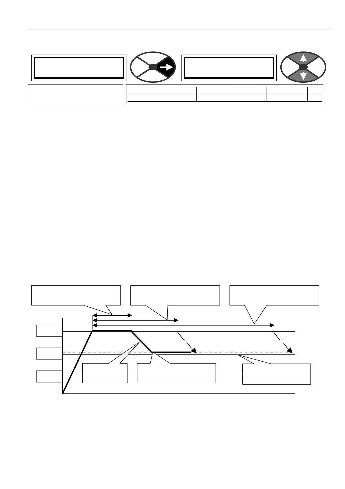
6.8.3.1.1 Diagram showing O/LO AD % T ARGET set to 105 %
Formula for calculating Dw ell time for a given PIN82 Overload % target and PIN1 38 prevailing Current Limit%
DWELL TIME = (150 %-PIN82%) x 25/(I limit%-PIN82%) in seconds. (Assuming current remains at the limit).
Formula for calculating Current limit setting required for a given PIN82 Overload % target and D WELL TIME.
Current limit% required = PIN82% + (150 % - PIN 82 %) x 25/DWELL TIME secs
Formula for calculating PIN82 Overload % target required for a given Current limit% and DWELL TIME.
PIN82 Overload % target = (D WELL TIME secs x Current limit % - 3750) / (D WELL TIME secs - 25)
CURRENT O VERLO A D 4
82)O/LO AD % T ARGET
82)O/LO AD % T ARGET
105.00 %
PARA METER RANGE DEFAULT PIN
O/LO AD % T ARGET 0.00 TO 1 05.00 % 10 5.00 % 82
Sets the current limit target
level after excessive overload.
150%
100%
50%
82)O/LO AD % T ARGET
set to 105.00 %
DWELL TIME = 2 5 secs if
Iarm = 150.00%. See formula
83)O/LO A D
RA MP TIME
2)RA TED ARM A MPS
Equivalent to 100 %
If Iarm = 1 27.50% then time
to limit reduction = 50 secs
If Iarm = 1 16.25% then time
to limit reduction = 100 secs