98 CHA NGE PARA METERS
CURRENT C ON TROL 3
CURRENT O VERLO A D 4
CURRENT O VERLO A D 4
83)O/LO A D RA MP TIME
CURRENT O VERLO A D 4
82)O/LO AD % T ARGET
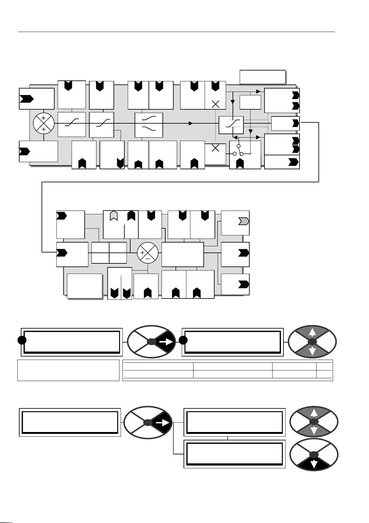
6.8.1 CURRENT C ON TROL / Block diagram
6.8.2 CURRENT C ON TROL / Current clamp scaler PIN 81
6.8.3 CURRENT C ONTROL / CURRENT OVERLO A D
CURRENT C ON TROL 3
81)CUR CLA MP S C ALER
81)CUR CLA MP S C ALER
150.00 %
PARA METER RANGE DEF AULT PIN
CUR CLA MP SC ALER 0.00 to 150.0 0% 150.00 % 81
Sets the clamp scaling value
for the upper/lo wer clamps.
R
R
PIN 91
Extra
Current reference
Current reference
Input
C onnected
from speed control
PIN 82
Overload
% target
PIN 83
Overload
Ramp
time
PIN 84
Dynamic
profile
PIN 3
Current
Limit %
Calibration
Menu
PIN
88
Dual cur
Clamp
Enable
I limit %
+ /- clamps
PIN 87
Dynamic
profile
PIN 86
Dyn profile
Low I spd
break point
PIN 85
Dyn profile
High I spd
break point
Scaler
PIN 81
PIN 89
Upper cur
clamp
Scaler
PIN 81
Scaled user -ve
Clamp PIN 137
Prevailing -ve
Clam
PIN 1 39
At limit flag
PIN 14 1
To current
Error amp
Inverter
-1
Scaled user + ve
Clamp PIN 136
Prevailing + ve
Clamp PIN 138
PIN 140
Overload
Limit
monitor
CURRENT
CO NTROL (Clamps)
PIN 90
Low er
current
clamp
CURRENT
CONTROL
( P + I)
C urrent
Demand
Input
from current
control clamps
Armature
Current
Feedback
PIN 93
Prop
Gain
PIN
96
4 Q mode
(Regen only
if model
allows)
Q 2 + I Q1
-v + v
Q 4 -I Q 3
PIN 94
Integral
Gain
PIN 95
Discontinuous
Current point
Armature
Stack
Firing
Angle
output
PIN 92
Autotune
enable
Current error amp
P + I
Current
Loop off
Warning
Hidden
PIN 70 4
+ Armature
Bridge
Flag
PIN 165
Arm mon
Amps %
PIN PIN
13 5 1 34
C urrent demand
PIN PIN
71 8 133
Unfiltered
PIN 678
Max curr
Response