Basic application 37
4.3 Main contactor wiring options
There are various w ays of implementing contactor control. Each method has advantages and disadvantages.
Please study the rest of this section carefully before choosing the control method.
See also 14.9.1 Wiring diagram for A C supply to L1/2/3 different to EL1/2/3. (E.g. Low voltage field)
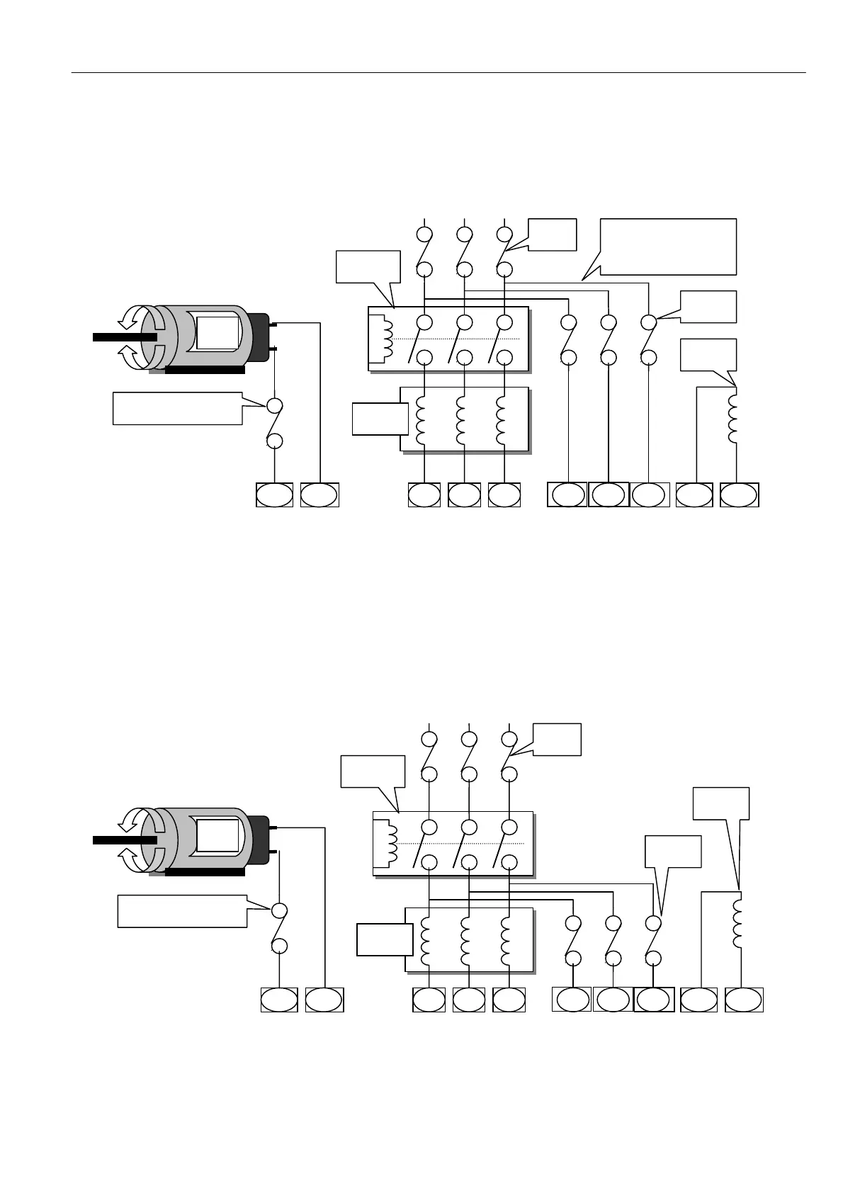
4.3.1 Main contactor isolating A C stack supply
Advantages The auxiliary supplies are permanently energised. This allows the synchronisation
circuits to lock onto the supply prior to the application of po wer to the motor. This results in a fast release of
current to the armature because it avoids the synchronisation delay. Also the field can remain energised after
contactor drop out, allo wing dynamic braking and/or condensation prevention in standby field mode.
Disadvantages The field winding is not electromechanically isolated by the main contactor, which
may contravene safety codes without additional measures. The field standby level may not be set to a lo w
enough level by the user and could cause overheating of the field winding. Phase forw ard may occur before
contactor has closed causing fault current. (Time delay from ST ART command to phase forward is 75mS.)
4.3.2 Main contactor isolating A C stack and auxiliary supplies
Advantages The field winding is electromechanically isolated by the main contactor. Some retro fit
installations are only able to provide the 3 main phases because the main contactor is remotely located to the
drive panel, in which case this wiring method may be preferred.
The PL/X cannot phase forw ard until the contactor has closed because EL1/2/3 take time to synchronise.
Motor
Arm
Line
reactor
L1 L2 L3
EL1 EL2
EL3
Main
Contactor
F- F +
Auxiliary
Fuses
Motor
Field
Main
Fuses
A + A-
EL1/2/3 are wired after the
main fuses to ensure the
phase loss function w orks if
a main fuse blow s
DC Semiconductor fuse for
regenerative applications
Line
reactor
L1 L2 L3
EL1 EL2
EL3
Main
Contactor
F- F +
Auxiliary
Fuses
Motor
Field
Main
Fuses
Motor
Arm
A + A-
DC Semiconductor fuse fo
regenerative applications