168 CONFIGURA TION
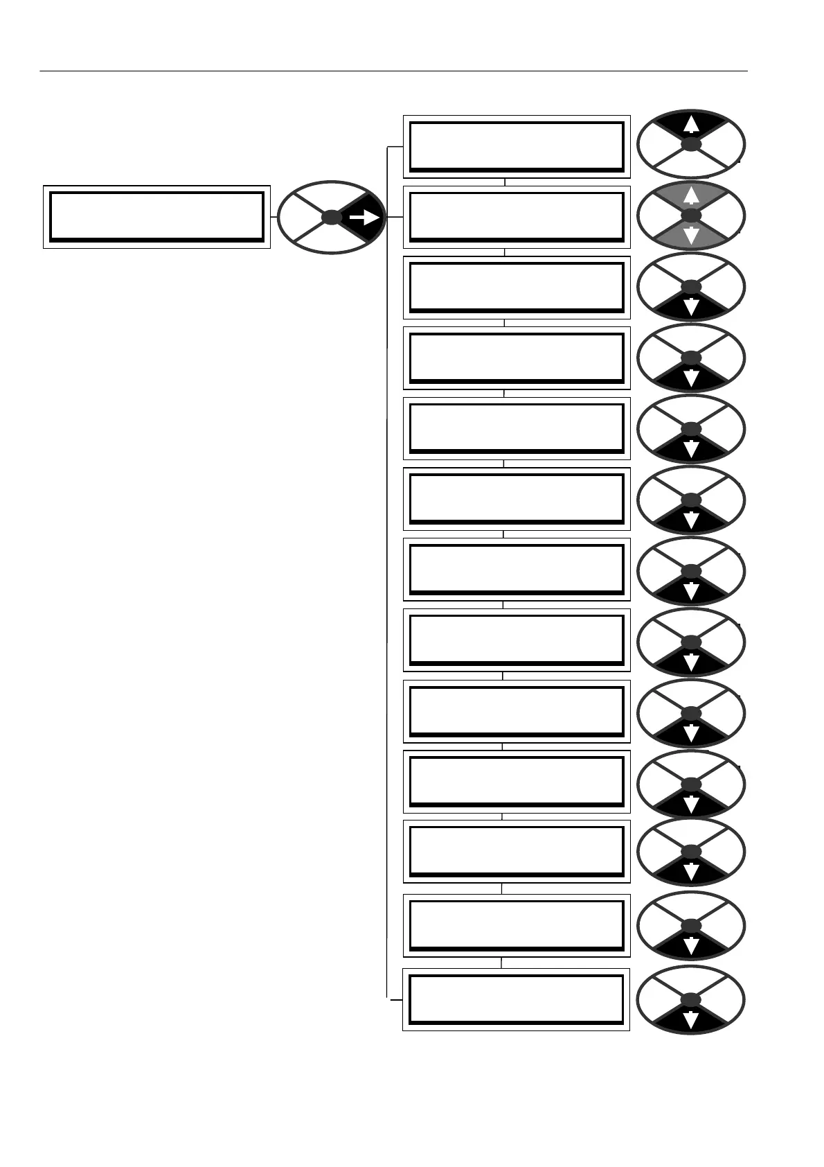
ENTRY MENU LEVEL 1
CONFIGURATION 2
CONFIGURA TION 2
CONFLICT HELP MENU 3
CONFIGURA TION 2
ENABLE G OT O, GETFRO M
CONFIGURA TION 2
UNIVERSAL INPUTS 3
CONFIGURA TION 2
ANALO GUE OUTPUTS 3
CONFIGURA TION 2
DIGIT AL INPUTS 3
CONFIGURA TION 2
DIGIT AL IN/O UTPUTS 3
CONFIGURA TION 2
DIGIT AL OUTPU TS 3
CONFIGURA TION 2
ST A GING POSTS 3
CONFIGURA TION 2
SOFTW ARE TERMIN ALS 3
CONFIGURA TION 2
JUMPER C ONNEC TIONS 3
CONFIGURA TION 2
BLO CK OP C ONFIG 3
CONFIGURA TION 2
FIELDBUS CONFIG 3
CONFIGURATION 2
DRIVE PERSON ALITY 3
13.1 CONFIGURATION menu
PIN numbers used 250 to 399.
There are 720 parameters
each with a unique PIN that is used in the process
of configuration. The PINs identify connection
points during configuration and can store values.
CONNECTIONS. It is possible to construct complex
systems by making connections to PINs. There are
2 connection tools available. These are GOT Os and
GET FROMs. When a parameter is given a value by
the programming procedure, or is using its default
value, it is important to understand how it is
affected after connection to another source using
the GOT O function. In this ca se the value is solely
determined by the source. The parameter can be
used as a diagnostic monitor of that source.
If the connection from the source is then removed,
the default or de sired value of the target must be
re-entered and save d via the keys or PL PILOT.
APPLICATION BLOCKS from the applications menu
are normally dormant. Connecting the output of a
block, using its GOTO, to a PIN other than 400,
activates it.
See also 10.2.5 Parameter exchange using ASCII
COMMS and 10.2.5.1 PL PILOT and SC A D A
(System Control And Data Acquisition) package.
13.1.1 PL PILOT configuration tool
PL PILO T, a self installing PC based graphical
configuration, monitoring and recipe manipulation
tool, which allo ws fast and easy adjustment, is
supplied with the unit on a CD. It may also be used
for up to 10 PL/Xs on one multidrop serial link.
There is a suitable cable supplied to connect the
PC COM 1 serial port to PL/X RS232 PORT1.
187)PORT1 BAUD RA TE. Set it to 19200 on the
target PL/X, and in ‘Options’ / ‘Setup COM Port’ in
PL PILOT.
188)PORT 1 FUN CTION. Set it to ASCII CO MMS on
the target PL/X. PL PILOT can configure and
monitor. See 10.1.4 How to use USB ports and
10.2.5.1 PL PILOT and SCADA (System Control
And Data Acquisition) package. For PL PILOT
version compatibility see 5.1.7 Finding the soft w are
version number of the unit. See also 5.3 Archiving PL/X recipes.
Note. PILOT is not subject to PASSW ORD control. See 11.2 DISPLAY FUN CTIONS / PASSW ORD CO NTROL.