CONFIGURA TION 169
13.2 Configurable connections
The internal connections within the PL/X may be re-configured using the display and keys, or PL PILOT.
Note. To start a connection configuration session ENABLE GOTO, GETFROM must be set to ENABLED.
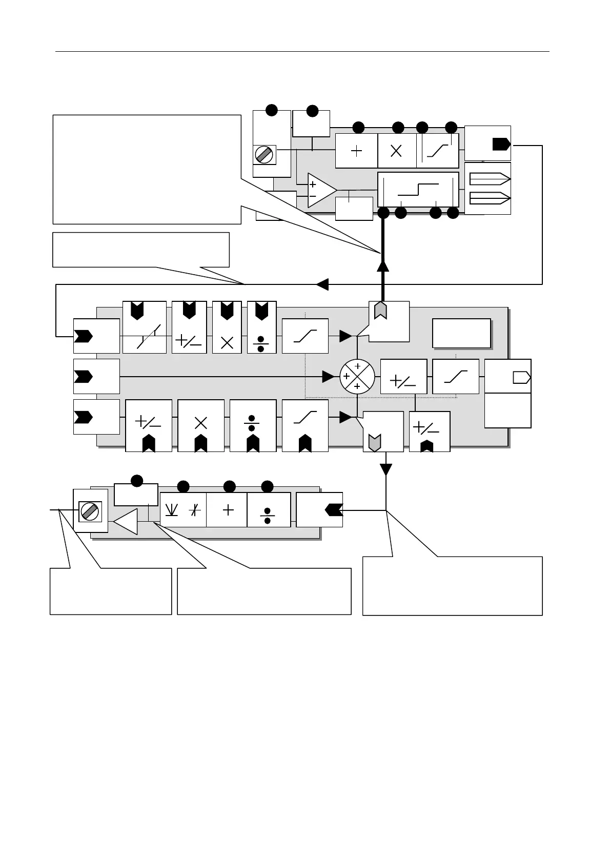
The PL/X possesses a versatile range of pre-designed BLOCKS. Signals need to be routed to the inputs of
the blocks, processed inside the block, then routed from the output to the desired destination. Examples of
blocks are a signal summer and a universal terminal input. There are 2 types of connection tool which can be
programmed by the user called GOTO and GET FROM. It is not possible to make illegal connections
e. g. from output to output. It is possible ho wever to connect more than 1 GO TO to a legal pin (eg an input)
and this would result in an error at the target PIN. The PL/X has a conflict checker which warns of GOT O
connection conflicts after configuration. (When the user sets EN ABLE GO TO, GETFROM to DIS ABLED).
See 13.14 C ONFLIC T HELP MENU. See also 13.8.1 Connecting PINs with different units.
Note. To end a connection configuration session ENABLE GOTO, GETFROM must be set to DISABLED.
Note. It is not possible to connect a G OT O directly to a GETFROM. To do this first connect the GO TO to a
ST A GING POST (or other unused PIN), then connect the GETFRO M to the same ST A GING POST.
A OP1
GET FRO M
T 1 0
PIN 252
Offset
PIN 253
Rect/Bipolar
PIN 251
PIN 159
OP monitor
This is a programmable GET
FROM connection made from a
block input to any other PIN
within blocks.
GO TO connection from a block
output to any PIN except outputs
This is an external
wire connection made
to a PL/X terminal.
This connection is made by
virtue of the design of the block
and is not programmable.
PIN 405
PIN 413
PIN 413
PIN 403
PIN 413
PIN 413
PIN 408
Input 1
PIN 412
PIN 401
Output
Pin
692
No di splay
Subtotal
out
ut
No di splay
Subtotal
output
Pin
6 91
PIN 410
Input 3
PIN 402
Input 2
Summer 1
PIN 413
PIN 413
PIN 407
Summer 1
GO TO
PIN 412
PIN
404
PIN
402
PIN
406
PIN
411
dead
band
Range
PIN 32 0
T2
UIP2
Input
AN ALO G
GO TO
PIN 322
Scaler
PIN 321
Offset
PIN 325 / PIN 32 7
High
Low
PIN 326 / PIN 32 8
GO TO OP1
High value1
Low value1
High value2
Low value2
GO TO OP2
PIN 16 2
Dig mon
Threshold
PIN
32 9
PIN 323
PIN 324
Analog
monitor
PIN 15 0
This is a universal programmable
connection device kno wn as a
JUMPER. It is basically a piece of
virtual wire with a GOT O at the
destination end and a GET FROM at
the source end. It can join any pair
of PINs including PINs within blocks
(There are 16 jumpers).