132 DIA GNOSTICS
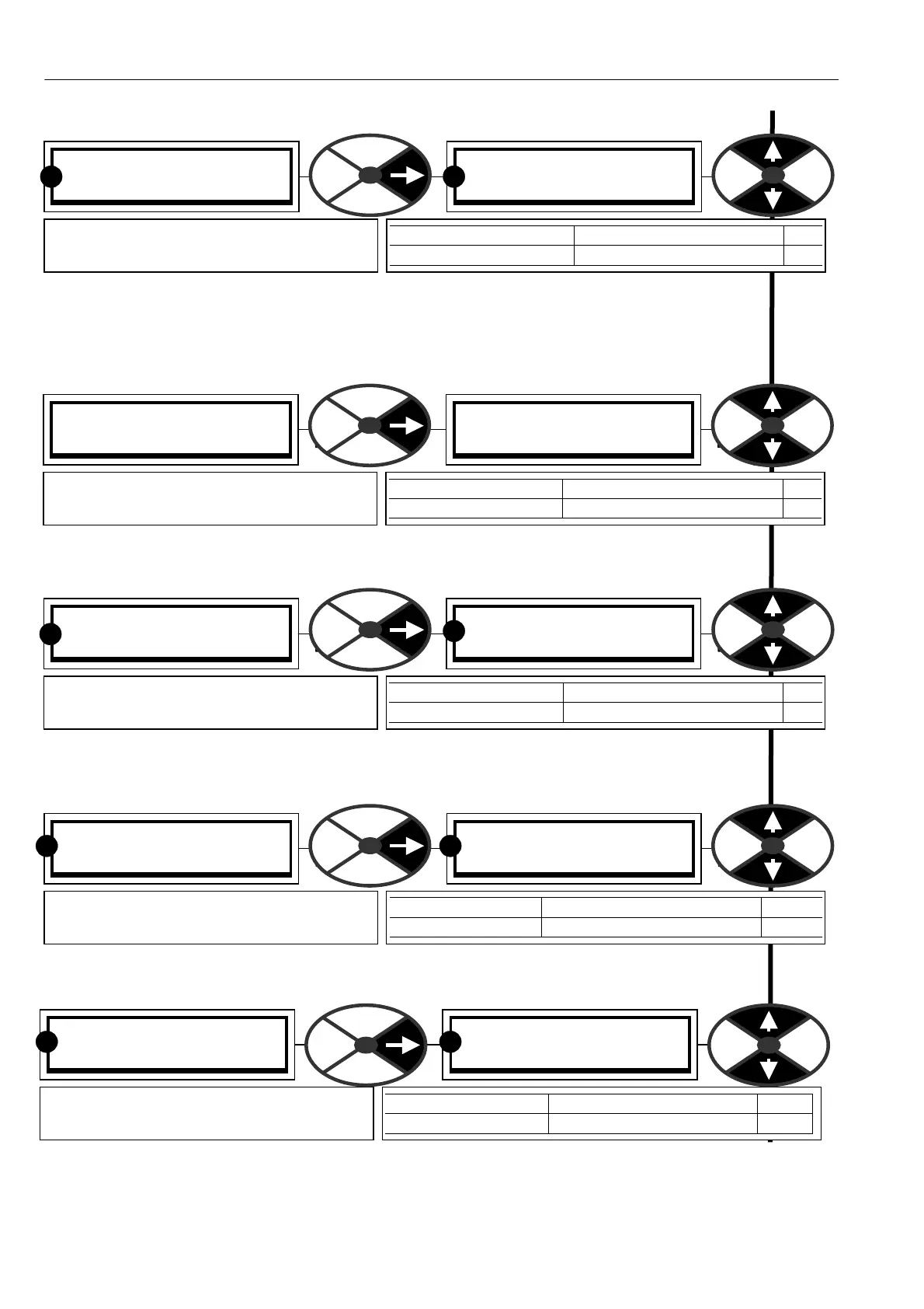
7.5.3 DIGIT AL IO M ONITOR / DOP1 to 3 + Control IPs digital monitor PIN 164
Note. The DOP value sho wn is the intended value. If the DOP is shorted, a 1 still sho ws as a 1.
Note. If this value is connected to another PIN then the pure binary to decimal equivalent is used.
(Most significant bit on the right, least significant on the left).
7.5.4 DIGIT AL IO M ONITOR / + Armature bridge flag PIN 165
7.5.5 DIGIT AL IO M ONITOR / Drive start flag PIN 166
7.5.6 DIGIT AL IO M ONITOR / Drive run flag PIN 167
7.5.7 DIGIT AL IO MONITOR / Internal running mode monitor PIN 168
Note. M ODE SELEC T (PIN 42) has a default connection from T15.
The 7 modes (with their numeric codes) displayed are (0 or 1) STOP (4) JO G SPEED 1
(5) JOG SPEED 2 (2) RUN (6) SLA CK SPEED 1 (7) SLA CK SPEED 2 (3) CRA WL
DIGIT AL IO MONITOR 3
165) + ARM BRID GE FLA G
165) + ARM BRID GE FLA G
LO W
PARA METER RANGE PIN
+ ARM BRIDGE FLAG HIGH + bridge, LO W-bridge 165
Shows whether the positive or negative
armature bridge is selected.
DIGIT AL IO MONITOR 3
167)DRIVE RUN FLA G
167)DRIVE RUN FLA G
LO W
PARA METER RA NGE PIN
DRIVE RUN FLA G HIGH (Run) or LOW (Stop) 167
Shows that a command to RUN has been
issued to the current loop.
R R
DIGIT AL IO MONITOR 3
168)RUNNING M ODE M ON
168)RUNNING M ODE M ON
STOP
PARA METER RANGE PIN
RUNNING MODE 1 of 7 modes displayed 168
Shows mode selected by START (T3 3),
JO G (T32) and MODE SELECT (PIN 42)
R R
DIGIT AL IO MONITOR 3
166)DRIVE ST ART FLAG
166)DRIVE ST ART FLAG
LOW
PARA METER RANGE PIN
DRIVE START FLA G HIGH (on) or LOW (off) 166
Shows the status of the internal drive
ST ART which may be defeated by alarms
R
R
DIGIT AL IO MONITOR 3
164)DOP 1 2 3 T R J S C C IP
164)DOP 1 2 3 T R J S C C IP
0 0 0 0 0 0 0 0
PARA METER RANGE PIN
DOP 1 2 3 T R J S C C IP 0/1 for 8 signals (0 = low) 164
Shows the digital logic level for DOP1 to 3
and Therm, Run, Jog, Start, Cstop
R R