DIA GNOSTICS 131
DIGIT AL IO MONITOR 3
169)RUNNING M ODE M ON
DIGIT AL IO MONITOR 3
162)UIP 2 3 4 5 6 7 8 9
DIGIT AL IO MONITOR 3
163)DIP 1 2 3 4 1 2 3 4 DIO
DIGIT AL IO MONITOR 3
164)DOP 1 2 3 T R J S C C IP
DIGIT AL IO MONITOR 3
165) + ARM BRID GE FLA G
DIGIT AL IO MONITOR 3
166)DRIVE ST ART FLAG
DIGIT AL IO MONITOR 3
167)DRIVE RUN FLA G
R
R
R
R
DIA GNOSTICS 2
DIGIT AL IO MONITOR 3
R
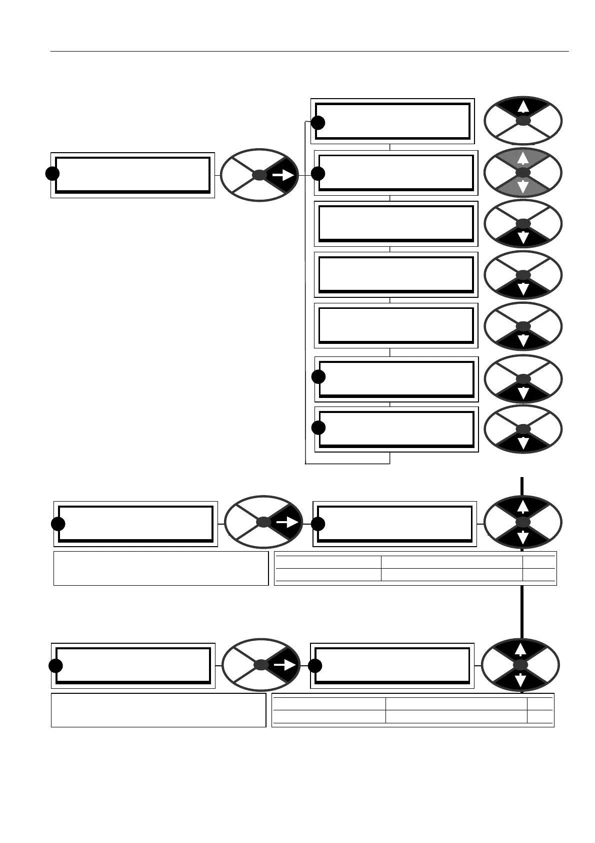
7.5 DIAGNOSTICS / DIGITAL IO
MONITOR
PIN number range 162-1 69
This menu allows monitoring of the digital input
and output functions.
Universal inputs are UIP2 to UIP9. (UIP1 is used
internally and not available on a terminal).
UIP2 to 9 are universal inputs and can be used as
digital and/or analogue inputs. The digital logic
level alw ays appears in this menu and the analogue
value will simultaneously appear in the analogue IO
monitor menu.
The logic inputs are arranged in groups and can be
vie wed together in one windo w.
7.5.1 DIGIT AL IO MONITOR / UIP2 to 9 digital input monitor PIN 162
Note. If this value is connected to another PIN then the pure binary to decimal equivalent is used.
(Most significant bit on the right, least significant on the left).
7.5.2 DIGIT AL IO MONITOR / DIP1 to 4 and DIO 1 to 4 digital input monitor PIN 163
Note. If this value is connected to another PIN then the pure binary to decimal equivalent is used.
(Most significant bit on the right, least significant on the left).
DIGIT AL IO MONITOR 3
162)UIP 2 3 4 5 6 7 8 9
162)UIP 2 3 4 5 6 7 8 9
0 0 0 0 0 0 0 0
PARA METER RANGE PIN
UIP 2 3 4 5 6 7 8 9 0/1 for each UIP (0 = low) 162
Shows the digital logic level for UIP2 to 9.
Set the logic threshold in the config menu.
R R
DIGIT AL IO MONITOR 3
163)DIP 1 2 3 4 1 2 3 4 DIO
163)DIP 1 2 3 4 1 2 3 4 DIO
0 0 0 0 0 0 0 0
PARA METER RANGE PIN
DIP 1 2 3 4 1 2 3 4 DIO 0/1 for each IP (0 = lo w) 163
Shows the digital logic level present at the
DIP1-4 and DIO 1-4 terminals.
R R