130 DIA GNOSTICS
DIA GNOSTICS 2
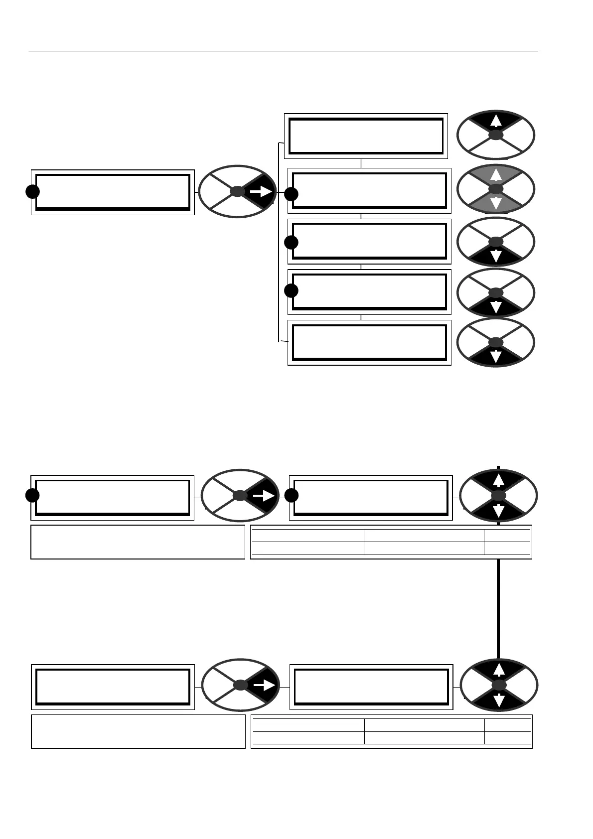
ANALO G IO MONITOR 3
R
ANALO G IO MONITOR 3
161)A OP3 (T 12) MON
ANALO G IO MONITOR 3
150)UIP2 (T 2) MON
ANALO G IO MONITOR 3
151)UIP3 (T 3) MON
ANALO G IO MONITOR 3
152)UIP4 (T 4) MON
ANALO G IO MONITOR 3
153 to160)UIP5 to11 MON
7.4 DIAGNOSTICS / ANALOG IO MONITOR
PIN number range 150 -16 1
This menu allows monitoring of the analogue input
and output functions.
Analogue inputs are UIP2 to UIP9. The
UIP number corresponds to its terminal number.
(UIP1 is used internally and not available on a
terminal).
UIP2 to 9 are universal inputs and can be used as
digital and/or analogue inputs. The analogue value
appears in this menu and the digital logic level will
simultaneously appear in the digital IO menu.
Note that the analogue output monitor for
A OP1/2/3 sho ws the value written to that output.
If the output is overloaded or shorted then the value
sho wn will not agree with the actual output.
The PL/X possesses a very useful commissioning tool, 260)SC OPE OP SELEC T. When enabled, this
automatically configures A OP3 on terminal 12 as an oscilloscope probe output. See 1 3.4.3 ANALO G
OUTPUTS / Scope output select PIN 260. The output is automatically connected to whatever parameter is
being displayed, and reconnected to its original source after the function is no longer enabled.
7.4.1 AN ALOG IO MONITOR / UIP2 to 9 analogue input monitor PINs 150 to 157
Note. There is a separate windo w for each input. The PINs are 150 to 157 for UIP2 to UIP9
The monitoring range depends on the UIP range selected. + /-5, + /-10, + /-20, or + /-30 V
Range for 5 V is + /- 5.3V Absolute accuracy worst case 0.4%, typically 0.1 %.
Range for 10V is + /-10.4 V Absolute accuracy w orst case 0.4%, typically 0.1 %.
Range for 20V is + /- 20.6 V Absolute accuracy worst case 4%, typically 1%.
Range for 30V is + /- 30.8 V Absolute accuracy worst case 4%, typically 1%.
7.4.2 A N ALOG IO MO NIT OR / A OP1/2/3 analogue output monitor PINs 1 59, 1 60, 161
Note. The analogue output monitor for A OP1/2/3 sho ws the value written to that output. If the output is
overloaded or shorted then the value sho wn will not agree with the actual output.
ANALO G IO MONITOR 3
150)UIP2 (T 2) MON
150)UIP2 (T 2) MON
0.000 VOLTS
PARA METER RANGE PINs
UIPX (TX) M ON + /-3 0.800 volts 150 - 7
Shows the analogue voltage for the
universal inputs 2 to 9.
R R
ANALO G IO MONITOR 3
159)A OP1 (T 10) MON
159)A OP1 (T 10) MON
0.000 VOLTS
PARA METER RANGE PINs
A OPX (TX X) M ON + /-11.300 volts 159-161
Shows the analogue output voltage for
A OP1/2/3 (PIN numbers 159, 160, 161)
R
R
R