180 CONFIGURA TION
CONFIGURATION 2
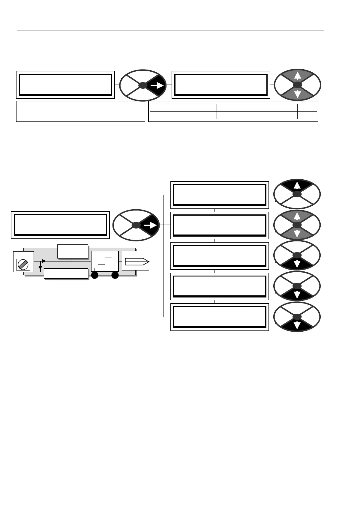
DIGIT AL INPUTS 3
DIGIT AL INPUTS 3
RUN INPUT SETUP 4
DIGIT AL INPUTS 3
DIP1 (T 14) SETUP 4
DIGIT AL INPUTS 3
DIP2 (T 15) SETUP 4
DIGIT AL INPUTS 3
DIP3 (T 16) SETUP 4
DIGIT AL INPUTS 3
DIP4 (T 17) SETUP 4
PIN 310
PIN 311
T 1 4
DIP monitor
PIN 163
DIPX
High value
Low value
GO TO
Encoder blocks
13.4.3 AN ALO G OUTPUTS / Scope output select PIN 260
The signal output is automatically switched to the displayed parameter, and provides a linear signed signal.
The output scale may be changed by using 257)AOP3 DIVIDER (default 100 % gives 10V). This allo ws very
rapid selection of the signal source for display on an oscilloscope.
Note. Any internal GETFROM connection made to A OP3 is left intact but ignored by 260)SC OPE OP SELECT
function.
13.5 CONFIGURATION / DIGITAL INPUTS
Pins 310 to 31 9
There are 4 digital logic inputs DIP1/2/3/4 on
terminals T14/15/1 6/17, plus the RUN input on
T31. The DIP inputs may also be used for
incremental encoder or register mark inputs. In
this case the logic functions will continue to
operate as described here.
The LO and HI values can be entered using the display and keys, or may be connected to other output PINs
using JUMPERS. This turns the function into a change-over switch for dynamic values. For logic only usage a
value of 0.00 % is read as a low. Any non zero + /- value is read as a high. Logic inversion is accomplished
by entering 0.00% in the value for HI windo w and 0.01% in the value for LO window.
13.5.1 Using DIP inputs for encoder signals.
Logic thresholds. 0 < 2 V, 1 > 4 V
Note. When using encoders with quadrature outputs it is very important that the phase relationship of the 2
pulse trains remains as close to 90 degrees as possible. If the encoder is not mounted and centered
accurately on the shaft, it can cause ske wing of the internal optics as the shaft rotates through 36 0 degrees.
This produces a severe degradation of the phase relationship on a cyclical basis. If the encoder appears to
gyrate as the shaft rotates you must rectify the problem before trying to proceed with commissioning. The
best w ay of checking the output is to use a high quality oscilloscope and observe both pulse trains for good
phase holding and no interference. Do this with the drive rotating to + /- 100 % speed using A V F as the
feedback source. Note. If a logic input with high noise immunity is required it is recommended to use a UI P.
See 6.1.10 C ALIBRA TION / ENCODER SC ALING for more information about encoder feedback.
ANALO G OUTPUTS 3
260)S COPE OP SELECT
260)S COPE OP SELECT
DIS ABLED
PARA METER RANGE PIN
SC OPE OP SELEC T EN ABLED or DIS ABLED 260
Enables A OP3 to output the value of the
parameter in any display window.