CHA NGE PARA METERS 65
C ALIBRA TIO N 3
ENCODER SC ALING 4
ENCODER SC ALING 4
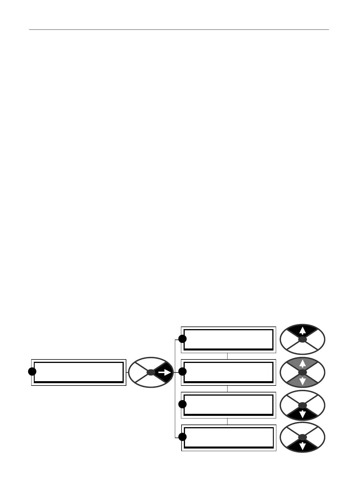
13)ENC ODER SIGN
ENCODER SC ALING 4
10)QU A DRA TURE EN ABLE
ENCODER SC ALING 4
11)ENC ODER LINES
ENCODER SC ALING 4
12)M OT/ENC SPD RA TIO
R R
R
R
R
the user must provide some external conditioning circuitry. The output format may be pulse only for single
direction, pulse with sign, or phase quadrature. See 6.1.10 C ALIBRA TION / ENCODER S C ALING.
There is an encoder failure detection system that may be configured to either trip the drive, or automatically
switch to A VF. See 8.1.1 MOT OR DRIVE ALARMS / Speed feedback mismatch trip enable PIN 171.
3) ENCODER + ARM VOL TS. In this mode the A VF provides the main dynamic feedback, and the
encoder feedback is used to trim the accuracy to an extremely high level.
Note. Low frequencies give poor performance. The lower frequency limit of reasonable performance with
encoder + A V feedback is a 100 % input frequency of 2Khz ( e. g. 60 lines at 2000 rpm single pulse train or
30 lines at 2000 rpm for a quadrature encoder). With more lines the performance improves, with less the
dynamic stability degrades, particularly at lo w speeds.
In this mode, when using a non quadrature single line encoder, the feedback sign is automatically provided by
the A VF and T16 digital input is made free for other uses. (Unless zero speed lock is required. See 6.10.9
ZERO INTERLOCKS / SPINDLE ORIENTA TE. In this case T16 is still required for the encoder direction).
The final steady state 100% speed feedback RPM is determined from 6)DESIRED M A X RPM. The dynamic
scaling is derived from 18)RATED ARM V OLTS. These 2 full scale settings must correspond with each other
for optimum performance.
A V F feedback usually contains ripple, hence it is advisable to reduce the SPEED CONTROL loop gains with
A V F feedback selected. See 6.7.4 SPEED CONTROL / Speed proportional gain PIN 71.
There is an encoder failure detection system that may be configured to either trip the drive, or automatically
switch to A VF. See 8.1.1 MOT OR DRIVE ALARMS / Speed feedback mismatch trip enable PIN 171.
4) ENCODER + TACHO. In this mode the tachogenerator provides the main dynamic feedback, and the
encoder trims the accuracy to an extremely high level.
Note. Low frequencies give poor performance. The limit of reasonable performance with encoder + tacho
feedback is provided with a full speed input frequency of 2Khz (60 lines at 2000 rpm single pulse train or 30
lines at 2000 rpm for quadrature encoder). With more lines the performance improves, with less the dynamic
stability degrades, particularly at low speeds.
In this mode, when using a non quadrature single line encoder, the feedback sign is automatically
provided by the tacho and T16 digital input is made free for other uses. (Unless zero speed lock is required.
See 6.10.9 ZERO INTERLOCKS / SPINDLE ORIENT A TE In this case T16 is still required for direction.)
An encoder and/or tacho failure detection system may be configured to either trip the drive, or automatically
switch to A VF. See 8.1.1 MOT OR DRIVE ALARMS / Speed feedback mismatch trip enable PIN 171.
The final steady state 100% speed feedback RPM is determined from 6)DESIRED M A X RPM. The dynamic
scaling is derived from 8)MA X T A CH O V OLTS. These 2 full scale settings must correspond.
6.1.10 C ALIBRA TION / ENCODER SC ALING
The ENCODER SC ALING screen is the entry point
to a further sub-menu w hich performs the process
of setting the encoder parameters.
Note. See 7.1.9 SPEED LOOP MO NIT OR / Encoder
RPM monitor PIN 132 w hich shows the encoder
RPM irrespective of whether the encoder is being
used for feedback or not.
Note. With no encoder fitted you may ignore this
sub-menu.