66 CHA NGE PARA METERS
6.1.10.1 ENCODER SC ALING / Quadrature enable PIN 10
The encoder inputs on T16 and T17 can be programmed to accept 2 types of encoder pulse trains.
0) Pulse with sign. QUADRATURE (DISABLED). A single train of pulses on T17 with a rotation direction
logic signal on T16 (lo w for reverse, high for forward). The logic level may be inverted using the
13)ENC ODER SIGN parameter. Note. When this type of encoder is used in conjunction with A VF or tacho,
the feedback sign is automatically provided by the analog feedback and T 16 digital input is made free for
other uses. (Unless zero speed lock is required. See 6.10.9 ZERO INTERLO CKS / SPINDLE ORIENT A TE. In
this case T1 6 is still required for the encoder direction.). See 6.1.9 C ALIBRA TION / Speed feedback type
PIN 9 Q UICK ST ART.
1) 2 pulse tr ains in phase quadrature. QUADRATURE (ENABLED). The encoder provides 2 pulse trains
phase shifted by 90 degrees. They are nominated the A train (on T17) and the B train (on T16). The A train
should lead the B train for forw ard rotation, (positive demand) and B leads A for reverse. The drive
automatically decodes the quadrature information to produce a rotation direction sign. This may be inverted
using the 13)ENC ODER SIGN parameter.
Note. When using encoders with quadrature outputs it is very important that the phase difference bet ween
the 2 pulse trains remains as close to 90 degrees as possible. If the encoder is not mounted and centered
accurately on the shaft, it can cause ske wing of the internal optics as the shaft rotates. This produces a
severe degradation of the phase relationship on a cyclical basis. If the encoder appears to gyrate as the shaft
rotates you must rectify the problem before trying to proceed with commissioning. The best way of checking
the output is to use a high quality oscilloscope and observe both pulse trains for good phase holding and no
interference. Do this with the drive rotating to + /- 100% speed using A VF as the feedback source.
Lo w frequency feedback may give poor results at low speed. Hence for encoders or other types of
pick up providing less than 15KHz at full speed it is recommended that mode 3 or mode 4 combined
feedback type is utilised. See 6.1.9 C ALIBRATIO N / Speed feedback type PIN 9 QUICK ST ART.
The encoder inputs have to be able to deal with and recognise very short pulses. This means that it is
not possible to provide heavy noise filtering on these inputs. Therefore it is very important that the signals
input on terminals 16 and 17 are clean and noise free.
One of the prime causes of un w anted noise on encoder signals is ground loops. If the encoder
electronics is earthed at the motor end then this may cause problems.
Make sure the encoder electronics 0 V is separately wired back to D0V on terminal 13, with no other
earth connections at the motor end.
The encoder casing will probably be earthed by virtue of its mechanical connection to the motor or
machine. This is usually acceptable as long as the internal electronics 0 V has a separate connection. Some
encoder manufacturers provide a by-pass capacitor inside the encoder between the electronics 0V and the
casing. Unfortunately the capacitor makes a very effective high frequency ground loop and may have to be
removed to prevent ground loop noise on the encoder signals. (Consult encoder supplier).
Ultimately it may be necessary to install an isolation link in the encoder loop.
Make sure the encoder cables are routed aw ay from heavy current or other noise generating cables. Use
insulated screened cable with a separate screen for each encoder signal connected at the drive terminal T13.
The encoder 0 V and + 24V should also be screened within the cable.
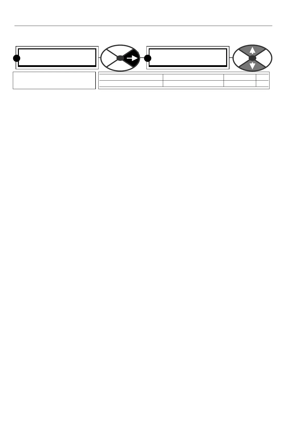
ENCODER SC ALING 4
10)QU A DRA TURE EN ABLE
10)QU A DRA TURE EN ABLE
ENABLED
PARA METER RANGE DEFAULT PIN
QUA DRATURE EN ABLE EN ABLED / DIS ABLED ENABLED 10
Programmes the encoder inputs
T16 and T17.
R
R