CHA NGE PARA METERS 67
6.1.10.2 ENC ODER SC ALING / Encoder lines PIN 11
The number of lines on the encoder dataplate should be entered. Alternatively enter the number of cycles of
high/low for one pulse train during one revolution. E. G. for a toothed gear wheel with 60 teeth and a
magnetic pick up, enter the number 60. Note that there is an upper frequency limit of 10 0 kHz.
6.1.10.3 ENCODER SC ALING / Motor / encoder speed ratio PIN 12
Note. The encoder is sometimes not fixed to the motor shaft, and may rotate at an RPM that is a non unity
ratio of the motor RPM. Some systems have the encoder geared up to obtain a higher feedback frequency.
MO T/ENC SPD RA TIO = Motor RPM / Encoder RPM (true for all speeds)
When using encoders it is advisable to initially run the system in A V F mode to verify the integrity of the
encoder feedback signals using an oscilloscope. Then after setting the QU A DRA TURE EN ABLE and EN CODER
LINES parameters, run the system in A VF feedback mode, and monitor 132)ENC ODER RPM in the
DIA GNOSTICS menu. This will verify the encoder operates as expected prior to using it as a feedback source.
Note. An encoder may be input and used for other tasks instead of feedback.
On hidden PIN 709)M OT OR RPM %, is the encoder feedback %, scaled to 100% = 6)DESIRED MA X RPM.
It is also scaled by 12)MOT/EN C SPD RA TIO w hich acts as a pure multiplying factor.
Both 132)ENCODER RPM and PIN 709)MOTOR RPM %, are purely encoder signals, that work independently
of the type of feedback selected. They both r ead zero wi th no pulses on the encoder inputs.
6.1.10.4 ENCODER SC ALING / Encoder sign PIN 13
Use this to invert the encoder feedback sign if needed. Note, in combined feedback modes type 3 and 4,
with single line encoders, the feedback sign is automatically taken from the A VF or tacho if SPINDLE
ORIENT A TE is not employed. (T16 digital input is made free for other uses).
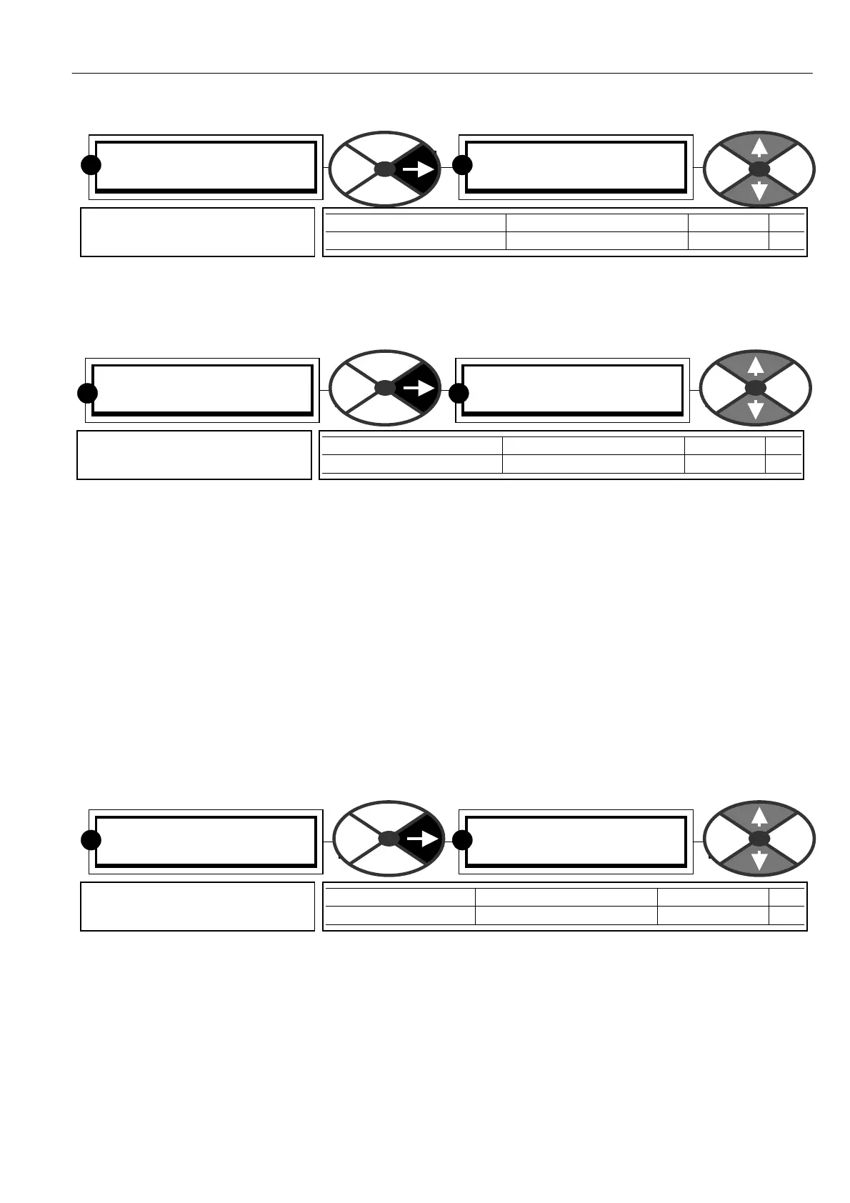
ENCODER SC ALING 4
11) ENCO DER LINES
11)ENC ODER LINES
1000
PARA METER RANGE DEF A ULT PIN
ENCODER LINES 1 to 6000 1000 11
Inputs the encoder resolution in
pulses per rev .
RR
ENCODER SC ALING 4
12)M OT/ENC SPD RA TIO
12)M OT/ENC SPD RA TIO
1.0000
PARA METER RANGE DEF A ULT PIN
MO T/ENC SPD RA TIO 0.0000 to 3.0 00 0 1.00 00 12
Sets the motor revs as a ratio
of the encoder revs.
R
R
ENCODER SC ALING 4
13)ENC ODER SIGN
13)ENC ODER SIGN
NON-INVERT
PARA METER RANGE DEF A ULT PIN
EN CODER SIGN NON-IN VERT or IN VERT NON-IN VERT 13
Modifies the encoder rotation
sign.
RR