CONFIGURA TION 173
UNIVERSAL INPUTS 3
UIP2 (T 2) SETUP 4
UIP2 (T 2) SETUP 4
329)UIP2 THRESHOLD
UIP2 (T 2) SETUP 4
320)UIP2 IP RANGE
UIP2 (T 2) SETUP 4
322)UIP2 C AL RATIO
UIP2 (T 2) SETUP 4
323)UIP2 M A X CLA MP
UIP2 (T 2) SETUP 4
324)UIP2 MIN CLAMP
UIP2 (T 2) SETUP 4
UIP ANALO G GOTO
UIP2 (T 2) SETUP 4
UIP DIGIT AL OP1 G OTO
UIP2 (T 2) SETUP 4
321)UIP2 IP OFFSET
UIP2 (T 2) SETUP 4
UIP DIGIT AL OP2 G OTO
UIP2 (T 2) SETUP 4
325)UIP2 HI V AL OP1
UIP2 (T 2) SETUP 4
326)UIP2 LO V AL OP1
UIP2 (T 2) SETUP 4
327)UIP2 HI V AL OP2
UIP2 (T 2) SETUP 4
328)UIP2 LO V AL OP2
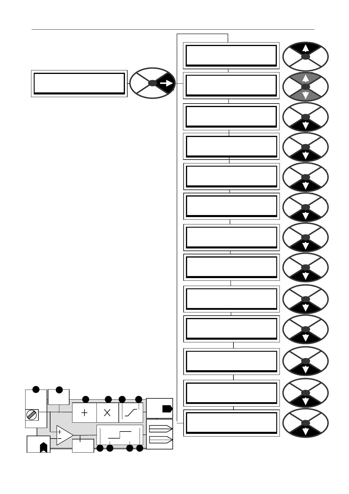
UNIVERS AL INPUTS / UIP2 to 9
This sho ws the UIP2 submenu
There are 8 sub menus, one for each
input 2 to 9
Each input terminal UIP2 to 9 is provided with its
own processing block with a linear and logic
output. It allows the following functions.
Range selectable + /- (5, 10, 20, 30V).
Linear functions.
Linear offset.
Signed scaling.
Clamping of the linear output.
Logic functions.
Adjustable threshold for logic level detection.
The comparator output is a low or a high. The
high state results in the HI V ALUE being output.
The low state results in the LO V ALUE output.
Note. UIPs offer good noise immunity.
The LO and HI values can be entered using the
display and keys, or may be connected from other
PINs using JUMPERS. This turns the function into
a change-over s witch for dynamic values.
There are 2 sets of value for high and value for
lo w windows each pai r having its own GOT O
connection facility. This allow s 2 independent
output values for a logic high input and 2
independent output values for a logic lo w input.
This facility allo ws versatile parameter changeover
functions to be selected by a single input.
E.g. DIG OP1 GOT O value change to target PIN x,
DIG OP2 G OT O simultaneous logic change to
target PIN y.
For logic only usage a value of 0.00% is read as a
lo w. Any non zero + /- value is read as a high.
Logic inversion is accomplished by entering
0.00% in the value for HI windo w and 0.01% in
the value for LO window .
Range
PIN 32 0
T2
UIP2
Input
AN ALO G
GO TO
PIN 322
Scaler
PIN 321
Offset
PIN 32 5 / PIN 327
High
Low
PIN 326 / PIN 32 8
GO TO OP1
High value1
Low value1
High value2
Low value2
GO TO OP2
PIN 16 2
Dig mon
Threshold
PIN
32 9
PIN 323
PIN 324
Analog
monitor
PIN 15 0