92 CHA NGE PARA METERS
MO T ORISED PO T RA MPS 3
52)UP TIME 4
CH A NGE PARA METERS 2
SPEED CONTROL 3
R
SPEED CONTROL 3
SPEED PI AD APTIO N 4
SPEED CONTROL 3
69)M A X POS SPEED REF
SPEED CONTROL 3
73)SPEED INT RESET
SPEED CONTROL 3
70)M A X NEG SPEED REF
SPEED CONTROL 3
71)SPEED PROP G AIN
SPEED CONTROL 3
72)SPEED INT T.C.
R
R
R
R
6.6.7 SPEED REF SUMMER / Speed/Current Reference 3 ratio PIN 67
The internal connection from UIP3 to 6 4)SPEED REF 3 MON is permanent. Ho w ever 64)SPEED REF 3 MON
may be disconnected from the SPEED REF SUMMER by setting 67)SPD/CUR RF3 RA TIO to 0.0000.
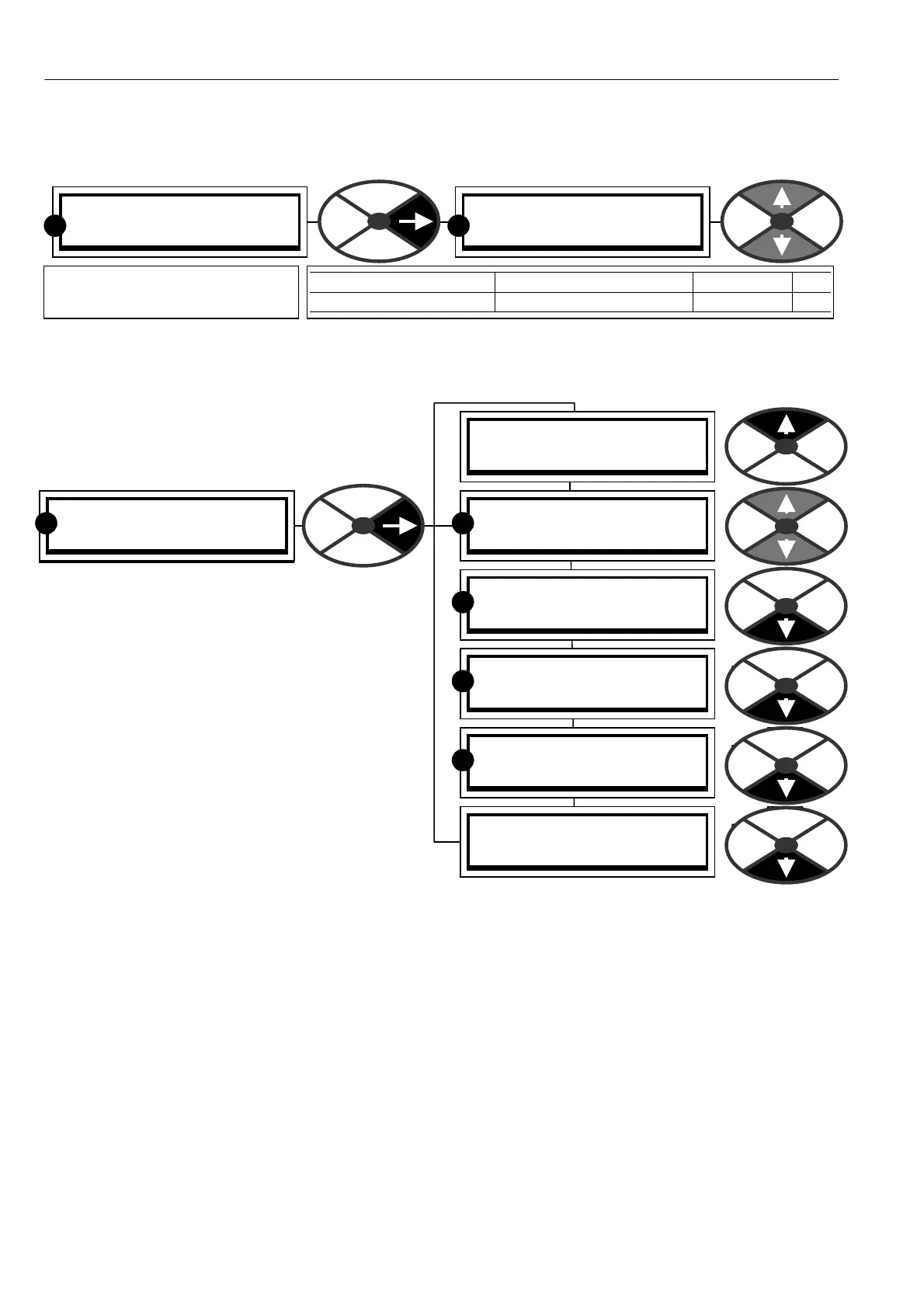
6.7 CHANGE PARAMETERS / SPEED CONTROL
PIN number range 69 to 7 9
This menu allows parameter adjustment for the
speed loop error amplifier. It consists of this list
and a sub menu called SPEED PI ADAPTION. This
menu refers to the block diagram below, starting
after the second summing junction. The summed
value of all the references is subject to a maximum
+ ve and -ve clamp. It then enters the stop mode
ramp block. This superimposes a ramp to zero at a
programmed rate on the prevailing input signal
during a stop command. When a run command is
received the output immediately assumes the level
then prevailing at the input. This level will normally
also be zero providing the run mode ramp block
has also been reset. The signal is then compared
with the speed feedback and processed by the
speed loop error amplifier.
The basic PI gain and time constants are adjustable in this list, and with further sophistication in the sub list
SPEED PI AD APTION. After being output from the error amplifier the signal no w represents current reference.
This current reference signal is then selected for output by the speed bypass change over s witch. If the
speed bypass mode is enabled then input reference 3 is selected.
Note. The default values in this menu have been chosen to suit tacho or encoder feedback. A V F feedback
usually contains more ripple than tacho or encoder feedback, hence it is advisable to reduce the SPEED
CONTROL loop gains whenever A VF or EN CODER + ARM V OLTS feedback is selected. See 6.7.4 SPEED
CONTROL / Speed proportional gain PIN 71.
In the case of A VF, it is suggested that the values for the follo wing parameters are changed as follow s.
6.7.4 SPEED CONTROL / Speed proportional gain PIN 71 set to 7.00.
6.7.7.6 SPEED PI AD APTION / Speed loop adaption enable PIN 79 set to DISABLED.
These are suggested starting points for smooth responsive control, however it may be possible to make
improvements with further experimentation.
SPEED REF SUMMER 3
67)SPD/CUR RF3 RA TIO
67)SPD/CUR RF3 RA TIO
1.0000
PARA METER RANGE DEF AULT PIN
SPD/CUR RF 3 RA TIO + /-3.000 0 1.0000 67
Sets a scaling factor for
Speed/current reference 3.
R
R