MOT OR DRIVE ALARMS 139
8.1.2 MOT OR DRIVE ALARMS / Speed feedback mismatch tolerance PIN 172
Note. If this value is set too lo w then spurious alarms may be caused by dynamic lags or non-linear effects.
Note. Mismatched calibration bet ween the A V F and tacho and/or encoder calibration erodes this margin.
Note. There is a flag on hidden PIN 703 which warns of a speed mismatch after the normal delay time.
This flag is reset by a start or jog command.
8.1.3 MOT OR DRIVE ALARMS / Field loss trip enable PIN 173
This alarm will normally trigger if the field current drops belo w 20% of rated current (5% in field w eakening
mode). Faulty operation of the field controller may also cause a motor field fail alarm. The most usual cause
for the motor field alarm is an open circuit motor field.
If this alarm occurs, the motor field connections should be checked and the field resistance measured.
The resistance of the field = dataplate field volts / dataplate field current.
WARNING. For rate d field currents that are less than 25% of model rating the a larm threshold may be too
low to trigger. The alarm must be teste d. To overcome thi s problem, 4)RATED FIELD AMPS may be set to a
higher level a nd 114)FIELD REFERENCE set lower. This has the effect of raising the threshold.
E.g. Set 4)RATED FIELD AMPS to twice motor rating and 114) FIELD REFERENCE to 50.00%.
If the PL/X is feeding a load which requires no field supply, for example a permanent magnet motor, then
99)FIELD EN ABLE should be disabled. This automatically inhibits the field fail alarm.
Alarm delay time: 2.0 0 secs.
8.1.4 MOT OR DRIVE ALARMS / Digital OP short circuit trip enable PIN 174
All digital outputs, and the 24 V user supply have been designed to withstand a direct short circuit to 0 V. If
this happens, an internal alarm is raised. The remaining digital outputs are also disabled resulting in a low
output. (Short circuit current is approximately 350mA for digital outputs and 400mA for + 24 V).
If the alarm is disabled and the shorting fault has not interrupted the drive running normally, then the drive
will continue to run. Note, if any digital output is shorted the + 24V terminal T35 will remain active with a
capability of 50m A. If the + 24V output is shorted then all digital outputs will also go lo w and this alarm is
activated. In this case if the + 2 4V is being used to enable CSTOP or START then the drive will stop.
MO TOR DRIVE ALARMS 2
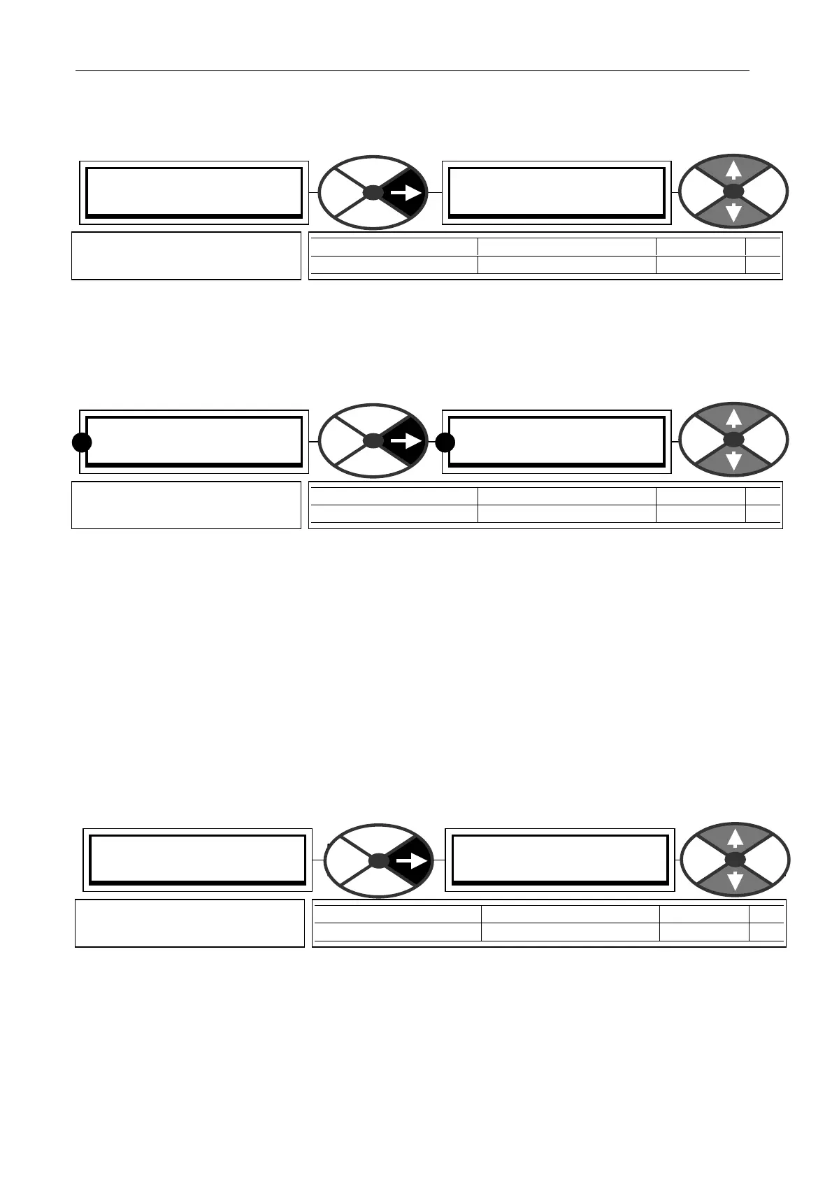
172)SPEED TRIP TOL
172)SPEED TRIP TOL
50.00 %
PARA METER RANGE DEF AULT PIN
SPEED TRIP T OL 0.00 to 100.00 % 50.00 % 172
Sets the speed feedback
mismatch trip tolerance.
MO TOR DRIVE ALARMS 2
173)FLD LOSS TRIP EN
173)FLD LOSS TRIP EN
EN ABLED
PARA METER RANGE DEF AULT PIN
FLD LOSS TRIP EN ENABLED OR DIS ABLED ENABLED 1 73
Allo ws the field failure alarm
trip to be disabled.
R R
MO TOR DRIVE ALARMS 2
174)DOP SCCT TRIP EN
174)DOP SCCT TRIP EN
DISABLED
PARA METER RANGE DEF AULT PIN
DOP SC CT TRIP EN EN ABLED OR DIS ABLED DISABLED 174
Allo ws the digital output short
circuit alarm trip to be enabled.