176 CONFIGURA TION
13.3.1.6 UIPX SETUP / UIP(2) to (9) Make analog G OTO destination connection
UI PX Term Analog GOTO Default connection name Defa ult connection
UIP2 2 Analog GOTO Aux speed reference PIN 63
UIP3 3 Analog GOTO Speed reference / Current demand (Fast IP)
(Internally connected, not using the G OT O)
PIN 400
(Block disconnect)
UIP4 4 Analog G OTO Ramp input PIN 26
UIP5 5 Analog GOTO Lower current clamp (-ve) PIN 90
UIP6 6 Analog GOTO Main current limit/Upper current clamp + ve PIN 89
UIP7 7 Analog GOTO Not connected PIN 400 (Default digital)
UIP8 8 Analog GOTO Not connected PIN 400 (Default digital)
UIP9 9 Analog GOTO Not connected PIN 400 (Default digital)
13.3.1.7 UIPX SETUP / UIP(2) to (9) Make digital output 1 GO TO destination connection
UIPX Term Dig OP1 GOTO Default connection name Default connection
UIP2 2 Dig OP1 GOT O Not connected PIN 400 (Default analog)
UIP3 3 Dig OP1 GOT O Not connected PIN 400
(Block disconnect)
UIP4 4 Dig OP1 GOT O Not connected PIN 400 (Default analog)
UIP5 5 Dig OP1 GOT O Not connected PIN 400 (Default analog)
UIP6 6 Dig OP1 GOT O Not connected PIN 400 (Default analog)
UIP7 7 Dig OP1 GOT O Motorised pot preset enable PIN 52
UIP8 8 Dig OP1 GOT O Motorised pot up command PIN 48
UIP9 9 Dig OP1 GOT O Motorised pot down command PIN 49
13.3.1.8 UIPX SETUP / UIP(2) to (9) Make digital output 2 GO TO destination connection
All UIP DIGIT AL OP2 GO TO default connections are 400)Block Disconnect.
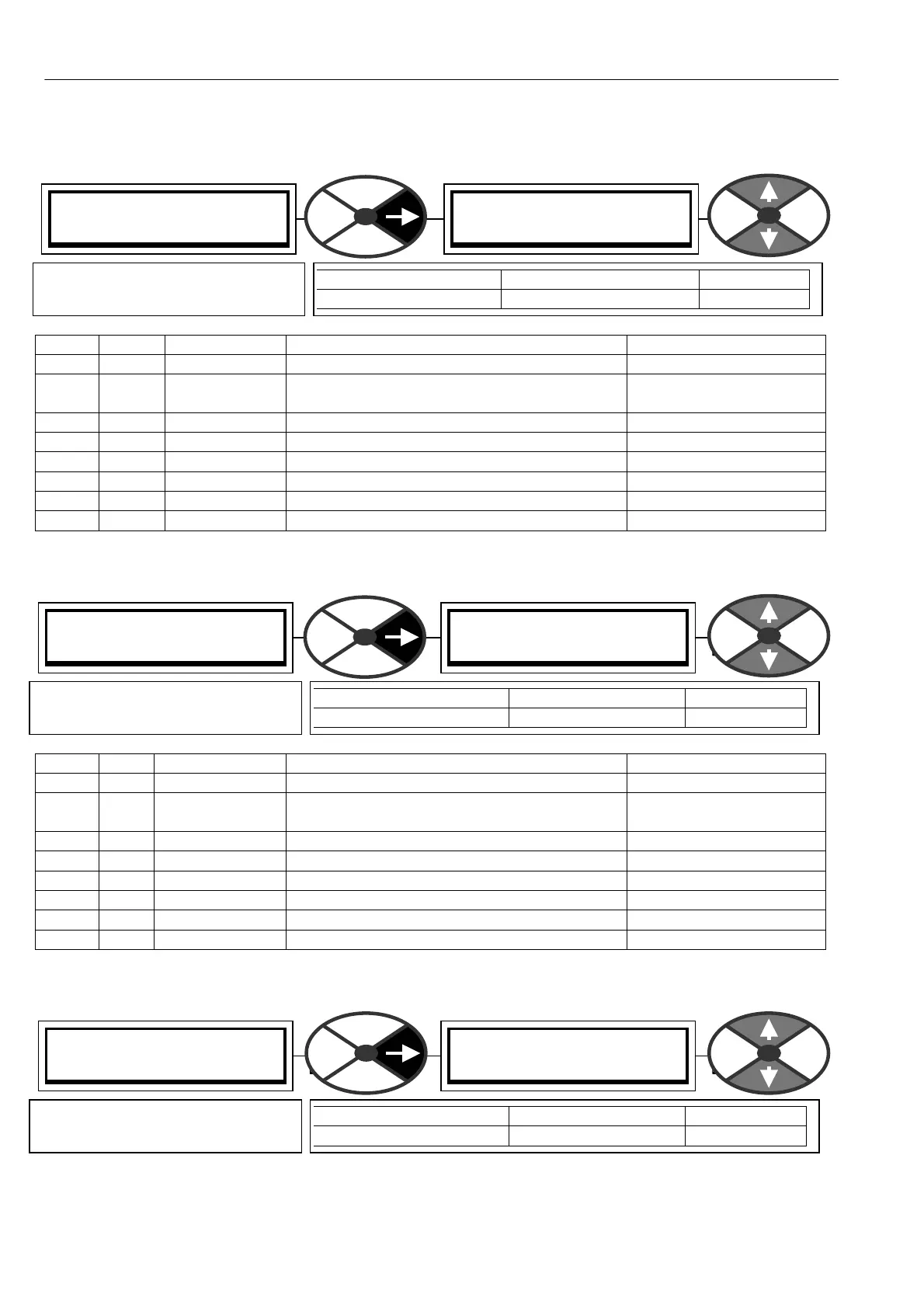
UIP2 (T 2) SETUP 4
UIP ANALO G GOTO
UIP ANALO G GOTO
PIN) Description of function
PARA METER RANGE DEF AULT
UIP ANALO G GOTO PIN 000 to 720 -See table.
Defines the target destination PIN
for the analog connection to UIPX
UIP2 (T 2) SETUP 4
UIP DIGIT AL OP1 G OTO
UIP DIGIT AL OP1 G OTO
PIN) Description of function
PARA METER RANGE DEF AULT
UIP DIGIT AL OP1 GOT O PIN 000 to 720 -See table.
Defines the target destination PIN
for the logic connection to UIPX.
UIP2 (T 2) SETUP 4
UIP DIGIT AL OP2 G OTO
UIP DIGIT AL OP2 G OTO
PIN) Description of function
PARA METER RANGE DEF AULT
UIP DIGIT AL OP2 GOT O PIN 000 to 720 400
Defines the target destination PIN
for the logic connection to UIPX.