200 CONFIGURA TION
13.13.4.2 W ARNING about changing BURDEN O HMS
It is important that the parameter 680)Iarm BURDEN OHMS, is set a s closel y as
possible to the actual resistance used on the power board. DO NOT ALLOW THE
MODEL RATI NG TO EXCEED THE VALUES IN THE RATING TABLE AND ON THE
RATING LABEL FOUND UNDER THE UPPER END CAP. FAI LUR E TO HEED THIS
WARNING WILL INVALIDATE ANY WARRANTY, AND VIOLATE APPROVAL
STANDARDS. NO LIABI LITY IS ACCEPTED BY THE MANUFACTURER AND/OR
DISTRIBUTOR FOR FAULTS CAUSED BY RE-RATING OF THE PRODUCT.
13.13.4.3 Changing control or pow er cards
Whenever it is necessary to replace either the control card or the power assembly, or transfer a control card
to a ne w po w er assembly then 68 0)Iarm BURDEN O HMS and the actual BURDEN OHMS must be re-checked
and 680)Iarm BURDEN OHMS changed if necessary according to the above procedures. See13.1 3.4
Removing the control card
First remove the plastic cover from the unit. To do this remove the end caps, then remove the 4 corner fixing
scre ws that retain the cover. When removing the cover please take care not to stress the display and key
connection ribbons. Unplug the ribbons from the control card to completely remove the top cover. The plugs
are keyed to ensure correct reconnection.
Then remove the t wo retaining scre ws at the lo wer corners of the control card. Lift the lower edge of the
control card up. The card hinges on the upper pair of plastic retainers. The only resisting force is due to the 2
X 20 interconnect pins in their sockets just above terminals T17 to T30. Once the pins have fully withdra wn
from their sockets, hinge the card gently a w ay to an angle of about 30 degrees. A t this point the upper
hinges are open and the card can be eased out of them.
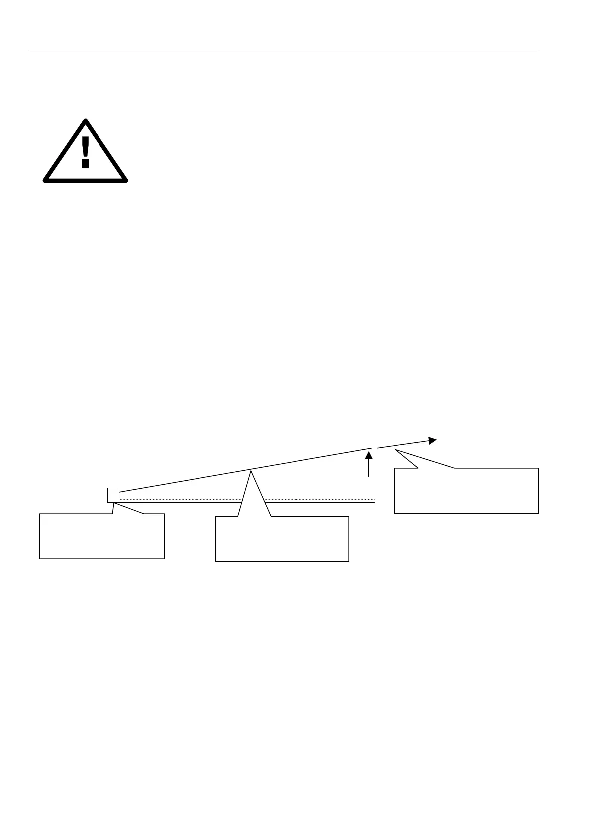
Side vie w .
To re-assemble, perform the above procedure in reverse order. The control card is guided by the hinges back
onto the interconnect pins. It is not possible to screw the control card flat unless the interconnect pins are all
correctly located.
WARNING. During IC insertion avoid bending the control card and causing damage. This is best achieved by
removing the control card and supporting it on a suitable surface. Special attention must be paid to provi ding
support to the card in the area of the IC being inserted, to avoid str essing the surrounding components.
Pair of hinges at top
edge with release gap
at about 30 degrees.
Control card hinged
a way from normal plane
by about 30 degrees
First lift up control card to
about 30 degrees then
withdra w it from hinges.