214 Installation
How ever when the difference becomes excessive it may be preferable to feed the 2 po wer ports from
different supply voltages. The reason for this is usually to prevent high peak voltages from being imposed on
a winding where the supply voltage is much higher than the winding rating. Also a winding that w as
designed to run at full voltage fully phased forw ard, will be subjected to a worse form factor when run
continuously phased right back, leading to overheating.
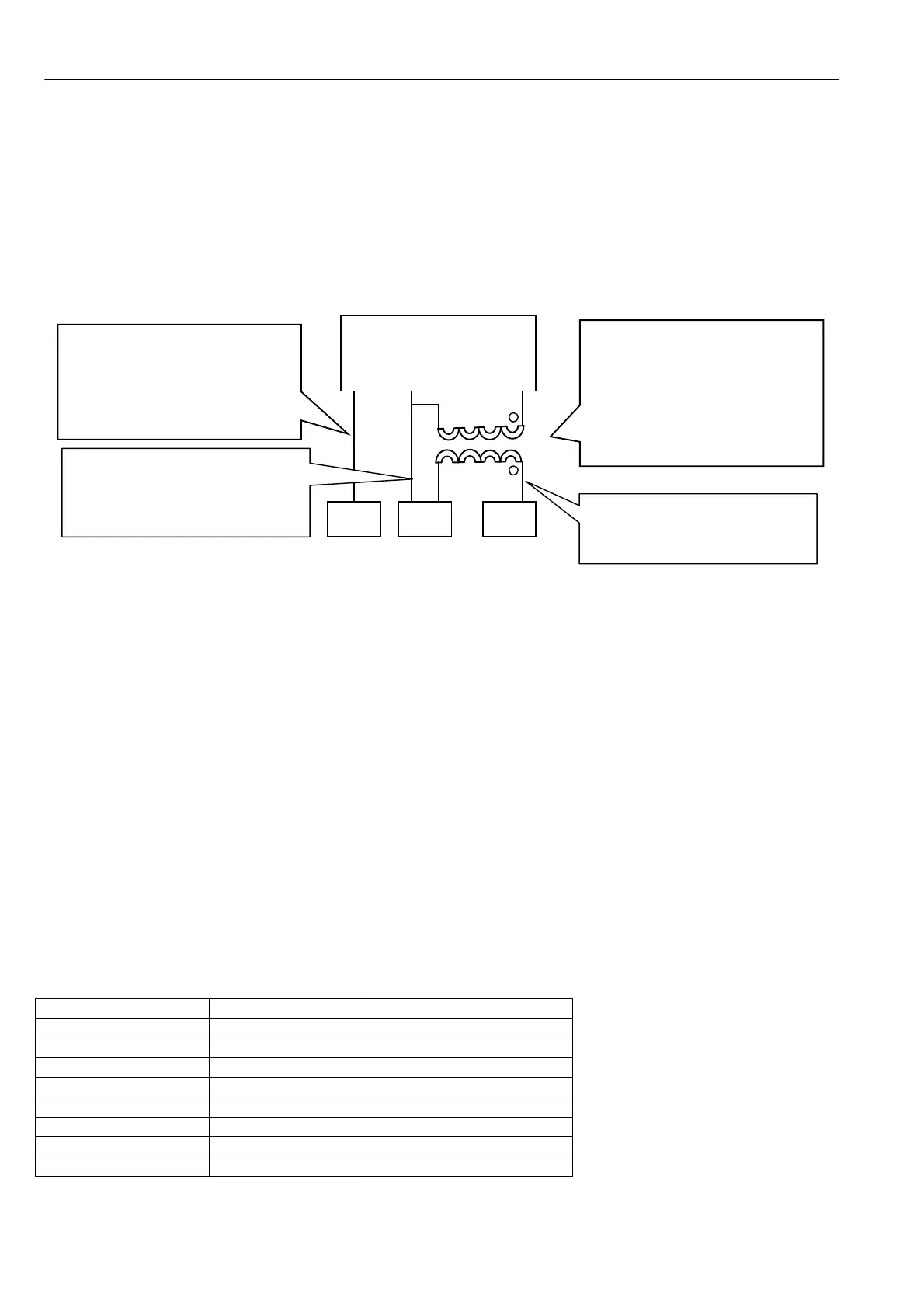
The wiring diagram below sho ws the preferred method of supplying the ports with different A C voltages.
It uses a single phase isolated transformer from L2 / 3 levels to EL2 / 3 to suit field.
E. g. The motor armature may be rated at 460 V DC to be supplied from a 41 5V A C supply, and the field
voltage may be rated at 100V DC, originally designed to be supplied from a rectified 110V A C supply.
The advantages of this method are: -
1) Only requires low cost easily available single phase transformer.
2) The EL1/2 connections do not suffer any phase lags or leads because they are still connected as per
standard schemes. This is important because the synchronisation is sensed through EL1/2.
3) This scheme works equally well for step up or do wn transformers.
4) The phase equivalence of EL1/2/3 must al ways relate to L1/2/3.
5) The inrush current of the transformer will probably blo w the semi-conductor fuses. Hence they should be
fitted on the secondary of the transformer for EL2/3. HRC fuses should be fitted in the primary feeds.
6) The field voltage required in the above example is 100V, probably originally designed to be operated from
a rectified 110 V supply. Ho w ever with the ability to control the field current available within the PL/X, it is
preferable to feed the field supply with a higher voltage, e.g. 130 V. This provides the control loop with a
supply margin in order to control more effectively.
WARNING. The field to earth voltage of the motor must be rated for the voltage appli ed to EL2.
4) See 6.1.16 C ALIBRATION / EL1/2/3 rated A C volts PIN 19 QUICK ST ART.
This must be set to the lower of the two AC voltages, which would be 130V AC in the above example.
WARNING. 8.1.11.11 DRIVE TRIP MESSAGE / Supply phase loss. This detector may then be ineffective for
loss of EL1. However 8.1.11.12 DRIVE TRIP MESSAGE / Synchronization loss will detect a loss on EL1.
5) See 4.3 Main contactor wiring options for details of wiring to L1/2/3 according to contactor requirements.
14.10 Terminal tightening torques
Terminals Model Tightening torque
Terminals 1 to 100 PL/X 5-265 4 lb-in or 0.5 N-m
EL1 EL2 EL3 F + F- PL/X 5-145 9 lb-in or 1.0 N-m
EL1 EL2 EL3 F + F- PL/X 185-265 35 lb-in or 3.9 N-m
L1 L2 L3 A + A- PL/X 5-50 35 lb-in or 3.9 N-m
L1 L2 L3 A + A- PL/X 65-2 65 242 lb-in or 27 N-m
Fan terminals PL/X 185-265 9 lb-in or 1.0 N-m
Plea se also refer to Part 3 PL/X 275-980 for extra details of frame 4 and 5 high power dri ves.
EL1 EL2 EL3
Isolated single phase step
do wn transformer is fed from
the phase equivalent of L2
and L3 provides 130V A C to
EL2 and EL3.
V A must be sufficient to
supply required field current.
3 phase supply at high
voltage. E.g. 460 V A C.
Phased as per L1/2/3
EL1 and EL2 supplied with
460V A C. Phase equivalent
to L1 and L2, and routed
according to preferred
contactor arrangement.
EL2 has high and low voltage
connections, made possible
because the transformer
secondary is floating.
EL2/3 semi-conductor fuses
fitted on the secondary of
the transformer. See note 5