58 CHA NGE PARA METERS
CH A NGE PARA METERS menu
There are a very large number of parameters that
can be altered by the user. All the alterable
parameters have a factory default setting that in
most cases wi ll provide a perfectly workable
solution and will not need altering.
One class of parameters that will need setting
ho wever is the C ALIBRA TIO N values. These are
special because they are used to set the maximum
ratings for the motor and drive.
The absolute maximum available armature current
of any particular model will not normally exceed the
C ALIBRA TIO N menu setting. If the control card is
transferred to a different pow er chassis it will
automatically interrogate the chassis to determine
the frame size. The user must make sure that if the
armature burden resistor value is different, then the
ne w value is entered into the unit. See 13.13.4
DRIVE PERSONALITY / Armature current burden
resistance PIN 680.
This allows owners of large numbers of drives to
hold minimal spares.
Sometimes it is useful to return a unit to its default
parameter condition. E.g. a trial configuration may
prove to be un workable and it is easier to start
again. If all 4 keys are held down during the
application of the control supply, then the drive will
automatically refer to the default parameters and
internal connections.
How ever parameters that are used to match the motor to the drive are not affected by restoring the defaults.
This includes all those in the CALIBRATION menu and 100)FIELD VOLTS OP %, (for MOTOR 1 and MOTOR
2) and 680)Iarm BURDEN OHMS. These parameters remain as previously calibrated to prevent accidental de-
calibration when restoring defaults. See 5.1.3 Restoring the drive parameters to the default condition
See also 13.13.2 DRIVE PERSON ALITY / Recipe page PIN 677, for details of 2 and 3 key reset operation.
This feature allo ws for 3 total instrument recipes to be stored and retrieved. W ARNING. Recipe page 2 and 3
each have their o wn set of calibration parameters, so be careful to check them all prior to running.
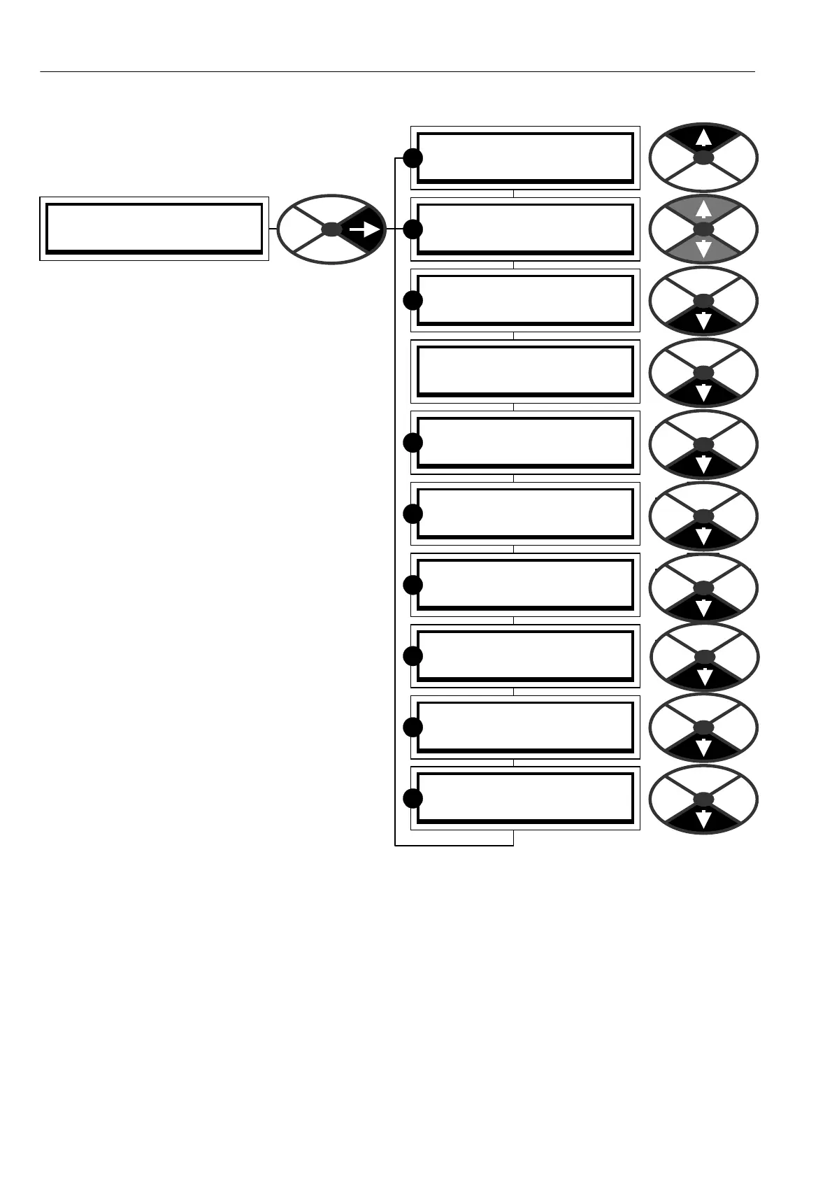
ENTRY MENU LEVEL 1
CH A NGE PARA METERS 2
CH A NGE PARA METERS 2
C ALIBRA TIO N 3
CH A NGE PARA METERS 2
RUN MODE RAMPS 3
CH A NGE PARA METERS 2
JO G CRA WL SLA CK 3
CH A NGE PARA METERS 2
MO T ORISED PO T RA MP 3
CH A NGE PARA METERS 2
STOP MODE RAMPS 3
CH A NGE PARA METERS 2
SPEED REF SUMMER 3
CH A NGE PARA METERS 2
SPEED CONTROL 3
CH A NGE PARA METERS 2
CURRENT C ON TROL 3
CH A NGE PARA METERS 2
FIELD C ONTROL 3
CH A NGE PARA METERS 2
ZERO INTERLO CKS 3
R
R
R
R
R
R
R
R
R