93
Thermocouple Measurement/Simulation, Connections and
Troubleshooting
To accurately measure the thermovoltage caused by the tempera-
ture to be measured, the second thermovoltage caused by the Ref-
erence Junction needs to be compensated. This is done using one
of the Reference Junction compensation methods described in the
subsequent chapters.
The Reference Junction compensation method has to be chosen
both when measuring and simulating thermocouples.
Internal Reference Junction
If the measuring/simulating port is set to
the Internal Reference Junction Module
(ET: TCi(mea) or ET: TCi(sim)), MC5P
automatically selects the Internal Refer-
ence Junction compensation method. No
other Reference Junction compensation
methods are available unless the measur-
ing/simulating port is changed.
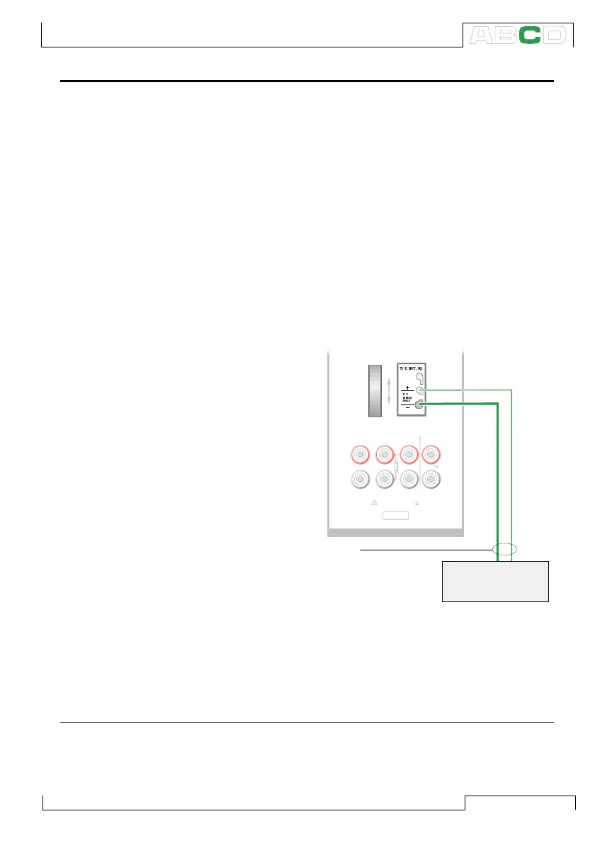
Connection when measuring/simulating
thermovoltage using Internal Reference
Junction Mode:
Note.
The range of the Internal Reference Junction’s temperature com-
pensation is -10 … +50°C (14 … 122 °F).
See also…
External Reference Junction on page 94
INTERNAL REFERENCE JUNCTION
FOR THERMOCOUPLES
Open
Close
Open
Close
T/C INT. RJ
T/C
WIRES
ONLY
S/N
Max 60 VDC/30 VAC
OUTPUTSENSOR MEASURE & SIMULATE
T/C, Low V
4-w meas
R, RTD
V,
I
,
3 & 4-w meas
T/C INT. RJ
T/C
WIRES
ONLY
T/C materials
(T/C, extension or
compensation wires)
T/C sensor
or a
T/C signal receiver
Additional Information