40
Startup and Basic Operation
Resistance Measurement
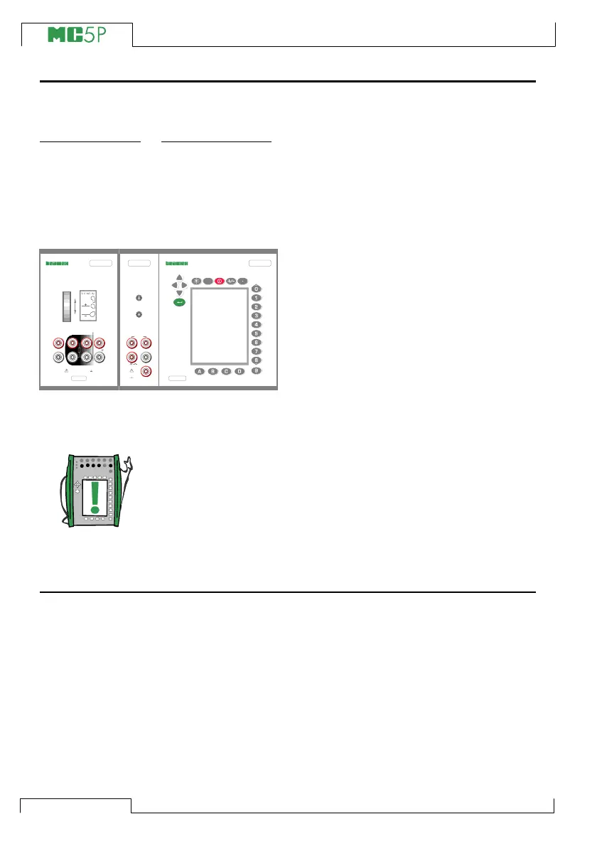
Resistance measurement terminals are located in the ET module.
Required settings Options/description
Quantity Resistance
Funct/Port ET: R(meas)
The following picture displays the active
terminals:
The two leftmost terminals are used in 2-
wire systems. MC5P automatically checks
the connection and displays the found wir-
ing system (2-wire, 3-wire or 4-wire) in the
measuring window. For more information
concerning wiring options, see Resistance
and RTD Measurement, Connections on
page 97.
Note.
If the measured resistance value is infinite or very high (> 4000 ohm),
the text “+OVER” is displayed in the measuring window. This means
that the circuit is broken or the connection is wrong. Wrong connec-
tion may also cause erroneous reading, typically too low. If neces-
sary, use the 2-wire ohm measurement to check the wiring before
final connection.
Next…
RTD and Resistance Simulation on page 62
RTD Measurement (Temperature) on page 46
Special Measurements on page 49.
Alarm Limit Settings on page 69.
Calibration, see Part D.
ELECTRICAL MODULE
FOR MC5P
S/N
MULTIFUNCTION CALIBRATOR
MC5PE
?
ET
ELECTRICAL AND TEMPERATURE MODULE
FOR MC5P
S/N
Max 60 VDC/30 VAC
Max 60 VDC
Max 30 VAC
OUTPUT
SENSOR MEASURE & SIMULATE
INTERNAL REFERENCE JUNCTION
FOR THERMOCOUPLES
T/C, Low V
4-w meas
R, RTD
V, I,
3 & 4-w meas
Open
Close
Open
Close
T/C INT. RJ
T/C
WIRES
ONLY
(ENV), ENVIRONMENTAL
TEMPERATURE SENSOR
(EXT), EXTERNAL
PRESSURE MODULE
MEASURE
+24V
I
meas/sink
HART
®
2-w xmtr
V, ,
Low V
Com