80
Advanced Operation and Configuration
Transmitter Simulation
Start the Transmitter Simulation as described in chapter Transmit-
ter/Switch Simulation on page 79. If the settings of the Basic Mode
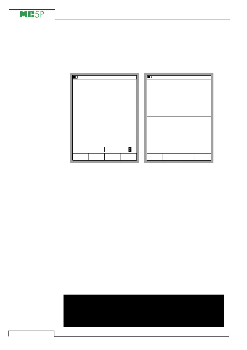
windows suit Transmitter Simulation, a configuration window simi-
lar to the lower left picture is shown.
Enter the input and output spans, the saturation limits and also the
transfer function.
If the saturation limits differ from the range limits, MC5P extrapo-
lates the output value based on the input value and the Transfer
Function until the saturation limit is reached. Then if the input signal
drifts farther from the input range, the output value stays at the satu-
ration limit.
The upper right picture shows the Basic Mode window while Trans-
mitter Simulation is active. The second row of both windows display
the active port and the input/output range of the simulated transmit-
ter.
Notes.
To Zero a pressure module during Transmitter Simulation, Press
D/MENU and 7/Zero Pressure Module.
When pausing the Transmitter Simulation, you can change the gen-
eration/simulation signal as in Basic Mode.
Warning!
Remember to scale the output signal of the Transmitter Simu-
lation so that the instrument connected to the output signal
loop is not damaged.
TRANSMITTER SIMULATION
11.11.2003 8:42
INPUT
Port
Pressure
P1:INT2C
kPa
Stop
Ramping
Field StartCancel Edit
100 %
kPa
0.000
100.000
Transfer Function
0 %
OUTPUT
Port
Current
E: I(control)
mA100 %
mA
4.0000
20.000
0 %
Saturation Limit Output Values
mAMaximum
mA
3.5000
23.000
Minimum
Linear
11.11.2003 8:43
P2: INT20C/ (0.00 ... 100.00 kPa g)
E: I(control)/ (4.0000 ... 20.000 mA)
gauge
kPa0.06
4.0000 mA
2
OUTPUT
1
INPUT
End
MENU
Measurement mA
4.0000
Pause
TRANSMITTER SIMULATION