96
Advanced Operation and Configuration
Error situations
The easiest way to avoid errors in thermocouple measurement and
simulation is to check carefully the used wiring and the Reference
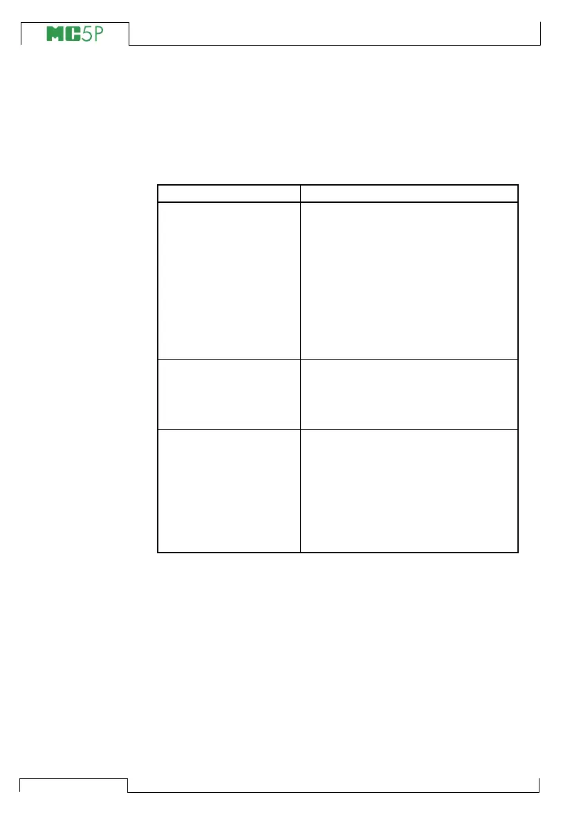
Junction mode. The following table describes the typical error situ-
ations and possible causes/corrections when working with thermo-
couples:
PROBLEM CAUSE
MC5P (or the instrument
under test when
simulating
thermovoltages)
measures the
temperature/millivolt
signal, but the displayed
temperature reading is all
wrong.
(The error may vary from
0 to about ±50°C
depending on the type of
the error)
• The thermocouple type selected in
MC5P does not correspond with the
used thermocouple.
•
The selected Reference Junction
mode is not in accordance with the
used wiring.
•
Extension or compensation cable type
or connections are incorrect.
•
The polarity of the cables are
incorrect.
MC5P (or the instrument
under test) displays
random readings during
thermocouple
measurement.
•
Incorrect connections.
•
The wiring is broken.
•
Interference from a mobile phone or a
radio transmitter affects the
measurement.
MC5P displays unstable
readings during
thermocouple simulation.
• The instrument under calibration uses
voltage pulses to detect open sensor.
When MC5P detects these pulses, it
tries to compensate for them, which
causes the unstable output. Prevent
these pulses for the time of
calibration. Refer to the service
manual of the instrument under
calibration on how to prevent these
open sensor detection pulses.