120
Calibration
Electrical Limit Switches
This procedure suits limit switches with an electrical input. The in-
put signal is generated with MC5P.
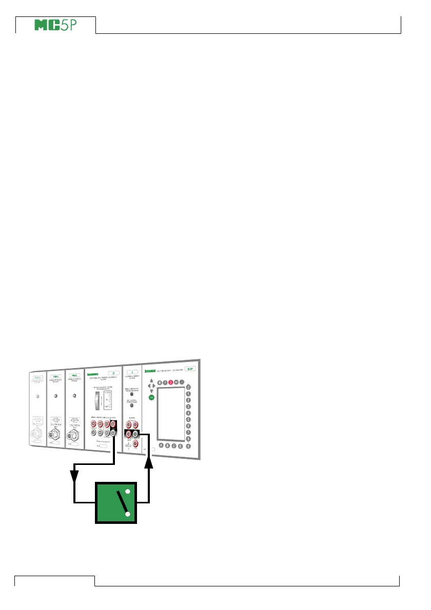
Required modules
• The ET module for generating the required electrical signal
(Voltage or Current).
• The E module for detecting the switch’s state.
Preparations
1. Connect the ET module’s terminals
marked “OUTPUT” to the input of the
switch.
2. Connect the switch contact to the switch
terminals in the E module.
3. Test the connections in Basic Mode if
needed. To quickly configure the Basic
Mode’s windows, go to Calibration
Mode, select the instrument to be cali-
brated and the Function Key C/Cali-
brate but immediately return to Basic
Mode.
Calibration
1. Move to Calibration Mode and select the
instrument to be calibrated.
2. Start the calibration as is presented in
chapter A Calibration Procedure Us-
ing MC5P on page 110. MC5P does the
Prescan if it is enabled. During the
prescan, MC5P searches for approxi-
mate values for the actuating and
deactuating point. This speeds up the
final test without sacrificing accuracy.
The prescan test is done only once in a
calibration.
• By default, the Prescan is set to on.
If you do not want MC5P to perform
a prescan, disable it (commands D/
MENU and 2/Prescan). When
Prescan is set to off, MC5P uses
the whole scan range also during
the actual test.
3. The actual test is done automatically:
MC5P slowly increases the input sig-
nal until the switch actuates and con-
tinues by decreasing the input signal
until the switch deactuates. MC5P’s
screen displays the obtained data as
the test advances.
XXXXXXX
XXXXXXX
+24V
V, ,
Open
CloseClose
T/C
WIRES
ONLY