EasyManua.ls Logo

CENNTRO LOGISTAR 100 - Page 188

Default Icon
468 pages
Print Icon
To Next Page IconTo Next Page
To Previous Page IconTo Previous Page
Loading...
Braking system
174
When removing any components or disconnecting pipelines, exhaust must be performed.
When replacing brake pads, the specified torque values apply to fasteners that are dry and
free of lubricating oil.
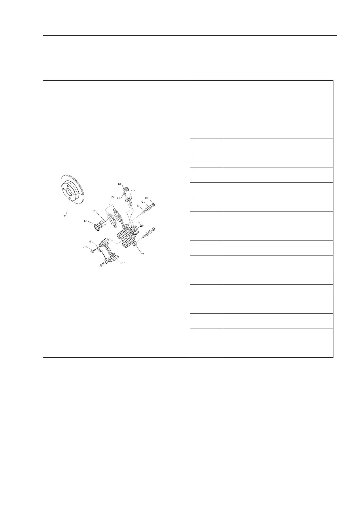
Schematic diagram
S/N
Name
1
Right rear brake caliper
assembly
2
Left rear brake caliper assembly
3
Brake caliper body
4
Brake disc
5
Steel wire compression spring
6
Friction block
7
Vent plug
8
Sliding shaft
9
Sliding shaft dust cover
10
Dust cover plug
11
Dowel
12
Parking push rod
13
Parking push rod spring
14
Mounting bracket bolt
15
Piston assembly
16
Piston sealing ring
17
Caliper mounting bracket

Table of Contents

Related product manuals