Power drive
Removal and installation
1. Turn the key switch to the "LOCK"
position and disconnect the negative
battery cable.
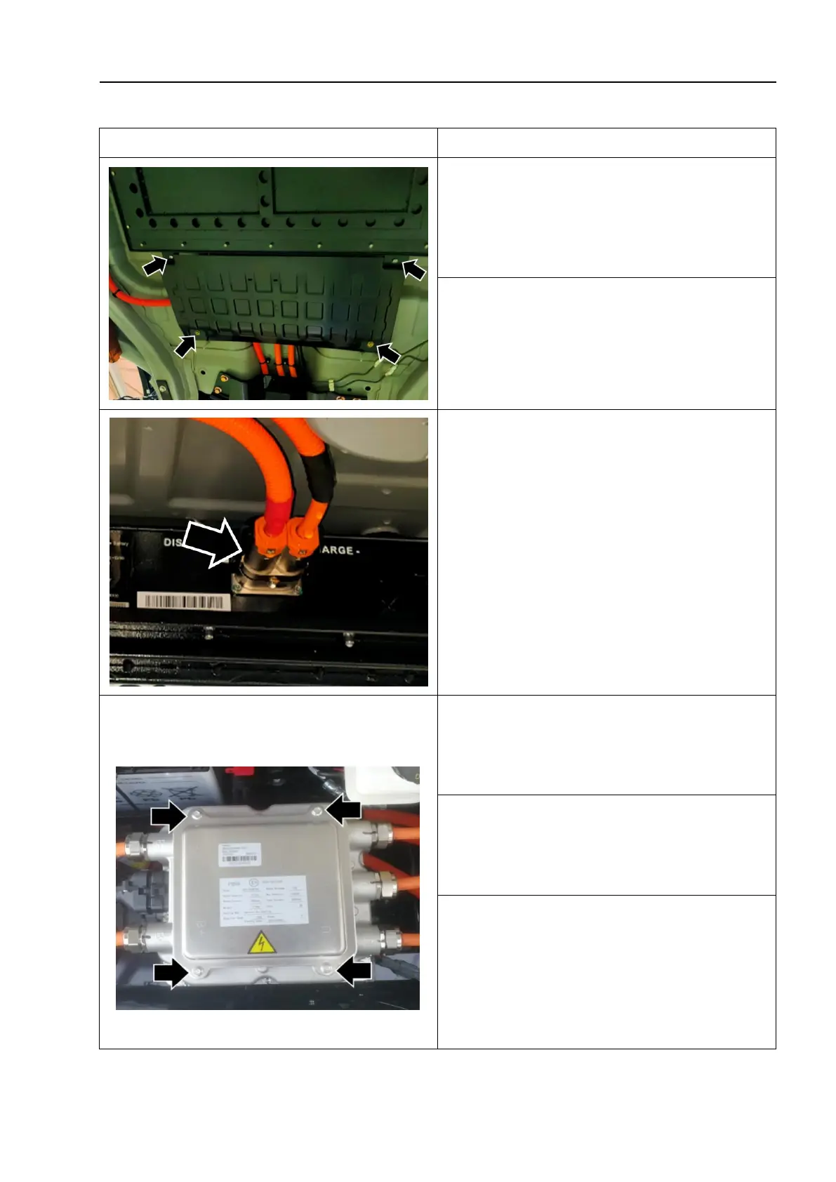
2. Unscrew the fixing bolts of the high voltage
wire protection plate - as shown by the arrow -,
and remove the high voltage wire protection
plate.
3. Disconnect the power battery high
voltage wire connection plug - as shown by
the arrow -.
4. Remove the left and right drive shaft
assemblies (refer to "Drive shaft removal
and installation").
5. Remove the electronic compressor
assembly (refer to "Air conditioning
compressor assembly removal and
installation").
6. Unscrew the fixing screw - as shown by the
arrow - and remove the upper cover plate of the
motor control unit- 1 -.
△
! Caution
When installing the cover plate,
confirm that the sealing strip is installed
correctly.